Beyond "Hello World": The Reality of LCD Integration
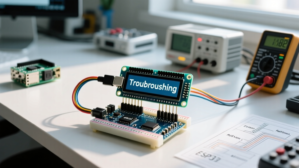
When you first learn to wire a 16x2 or 20x4 character display, the standard tutorial code works perfectly on a workbench. However, deploying an LCD in a real-world environment—such as an outdoor weather station, an industrial motor controller, or a home automation panel—introduces a host of physical and computational edge cases. Naive implementations of LCD display Arduino code often result in screen flicker, blocked main loops, I2C bus lockups, and rapid backlight degradation.
As of 2026, the supply chain for HD44780-compatible controllers has fully stabilized, bringing the cost of a generic 1602A I2C module down to roughly $3.50, while premium branded units like the DFRobot LCD2004 sit around $9.99. But hardware affordability doesn't solve software architecture flaws. To build robust sensor nodes, we must move past simple lcd.print() loops and engineer non-blocking, state-aware display routines.
Hardware Reality Check: I2C Backpacks and Address Conflicts
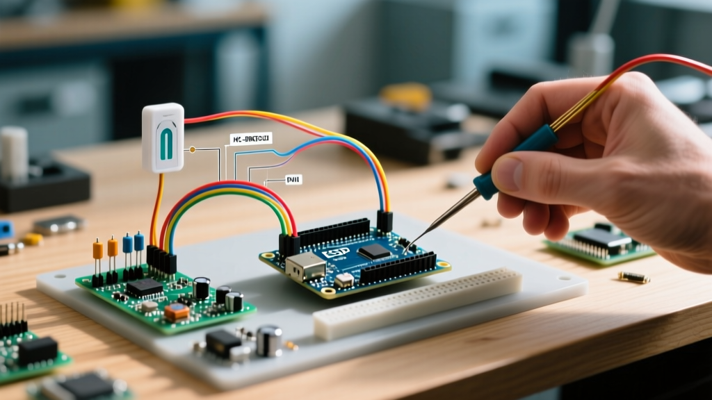
Almost all modern real-world deployments use an I2C backpack (typically based on the PCF8574 or PCF8574A I/O expander) rather than parallel wiring. This reduces the pin count from 6 to just 2 (SDA and SCL), freeing up microcontroller pins for sensors. However, this introduces the most common failure mode in LCD integration: address conflicts.
Expert Insight: The PCF8574T chip defaults to the I2C address
0x27, while the PCF8574AT chip defaults to0x3F. If you buy cheap, unbranded modules from online marketplaces, you will inevitably receive a mix of both. Hardcoding0x27in your LCD display Arduino code will cause silent failures on half your production batch.
To resolve this dynamically, we recommend abandoning the legacy LiquidCrystal_I2C library in favor of Bill Perry's hd44780 library. The hd44780 library automatically scans the I2C address space and auto-detects the exact pin mapping of the backpack, eliminating hours of manual troubleshooting.
The Architecture of Flicker-Free LCD Display Arduino Code
The most frequent mistake in sensor node programming is calling lcd.clear() followed by lcd.print() inside the main loop(). The clear() command takes approximately 1.5 milliseconds to execute on an HD44780 controller, but it forces the display to blank out momentarily, causing an aggressive, visible flicker. Furthermore, pushing data over I2C at 100kHz takes time, blocking your microcontroller from reading time-critical sensors.
The "Dirty Flag" and Overwrite Technique
Professional LCD display Arduino code relies on two principles:
- Dirty Flags: Only update the display when the underlying sensor data actually changes, or when a strict time interval (e.g., 250ms) expires.
- Targeted Overwriting: Instead of clearing the screen, overwrite only the specific characters that changed, padding with spaces if the new string is shorter than the old one.
Below is a production-ready architecture using a non-blocking update loop:
#include <Wire.h>
#include <hd44780.h>
#include <hd44780ioClass/hd44780_I2Cexp.h>

hd44780_I2Cexp lcd; // Auto-detects address and pin mapping

unsigned long lastDisplayUpdate = 0;
const int UPDATE_INTERVAL_MS = 250;
bool displayNeedsUpdate = false;

int previousTemp = 0;
int currentTemp = 0;

void setup() {
  lcd.begin(16, 2);
  // Print static UI elements exactly once
  lcd.print("Temp: ");
  lcd.setCursor(0, 1);
  lcd.print("Status: OK");
}

void loop() {
  // 1. Read sensor (simulated)
  currentTemp = readTempSensor();

  // 2. Set dirty flag only on state change
  if (currentTemp != previousTemp) {
    previousTemp = currentTemp;
    displayNeedsUpdate = true;
  }

  // 3. Non-blocking display update
  if (displayNeedsUpdate || (millis() - lastDisplayUpdate >= UPDATE_INTERVAL_MS)) {
    updateLCDDisplay(currentTemp);
    displayNeedsUpdate = false;
    lastDisplayUpdate = millis();
  }

  // Main loop remains free for other critical tasks
}

void updateLCDDisplay(int temp) {
  lcd.setCursor(6, 0); // Move to exact data position
  lcd.print("   ");     // Overwrite previous data with spaces
  lcd.setCursor(6, 0);
  lcd.print(temp);
  lcd.print("C");
}
Memory Footprint and Flash Constraints
When deploying on constrained microcontrollers like the ATmega328P (Arduino Uno/Nano) or ATtiny85, library bloat is a critical concern. The standard LiquidCrystal parallel library consumes roughly 2.2KB of flash memory. Switching to an I2C implementation adds the Wire library overhead, pushing total display-related memory usage close to 3.5KB. If your sensor node requires extensive local data logging or complex math, you must monitor your compilation output. Using the hd44780 library's diagnostic sketches can help strip out unused features and reclaim up to 400 bytes of precious SRAM.
Real-World Edge Cases: EMI, Capacitance, and Contrast Drift
Writing the code is only half the battle. The physical layer of the I2C bus dictates whether your LCD display Arduino code will survive outside the laboratory.
I2C Bus Capacitance and Pull-Up Resistor Tuning
The I2C specification limits bus capacitance to 400pF. In a real-world enclosure, running SDA and SCL lines through unshielded ribbon cables longer than 30cm introduces parasitic capacitance. This rounds off the sharp square waves of the digital signal, causing the Arduino Wire library to misinterpret bits, resulting in a frozen LCD.
According to the Texas Instruments PCF8574 datasheet, the I/O expander relies on external pull-up resistors. Most cheap LCD backpacks include 4.7kΩ resistors. For cable runs exceeding 30cm, you must desolder the 4.7kΩ surface-mount resistors and replace them with 2.2kΩ or even 1kΩ resistors to decrease the RC rise time and restore signal integrity.
Temperature-Induced Contrast Drift
The HD44780 controller's V0 (contrast) pin is highly sensitive to ambient temperature. A display perfectly tuned at 22°C will become completely unreadable at 5°C or 45°C. In professional deployments, we bypass the standard blue trim-potentiometer and use a PWM pin from the Arduino combined with an NTC thermistor to dynamically adjust the V0 voltage via a simple transistor circuit, ensuring readability across a -20°C to 60°C operating range.
Deployment Matrix: I2C vs. Parallel Interface
While I2C is the default choice for 90% of projects, specific environments demand parallel wiring. Use the following matrix to guide your hardware design:
| Feature | I2C Backpack (PCF8574) | Parallel (4-bit Mode) |
|---|---|---|
| Microcontroller Pins Used | 2 (Shared bus) | 6 (Dedicated) |
| Max Reliable Cable Length | ~50cm (without bus extenders) | ~15cm (high EMI susceptibility) |
| Update Speed | Slower (I2C protocol overhead) | Faster (Direct GPIO toggling) |
| EMI / Noise Immunity | Moderate (Requires shielded cable) | Poor (Parallel lines act as antennas) |
| Best Use Case | Multi-sensor nodes, enclosures | High-speed oscilloscopes, direct PCB mount |
Custom Characters: Maximizing the 64-Byte CGRAM
Real-world UI design often requires icons—battery levels, Wi-Fi signal bars, or specific warning glyphs. The HD44780 controller features a Character Generator RAM (CGRAM) that allows you to define custom 5x8 pixel characters. However, the CGRAM is strictly limited to 64 bytes, meaning you can only store eight custom characters at any given time.
If your sensor node requires more than eight icons, you must dynamically rewrite the CGRAM on the fly. Because writing to CGRAM is slow and interrupts normal display output, the best practice is to group your UI states. For example, store the "Battery Charging" and "Battery Full" icons in the same CGRAM slot, overwriting the byte array only when the power management state transitions.
Summary
Writing reliable LCD display Arduino code for real-world sensor nodes requires a holistic approach that bridges software architecture and hardware physics. By implementing dirty-flag update loops, utilizing auto-detecting libraries like hd44780, and actively managing I2C bus capacitance, you transform a fragile workbench prototype into a resilient, field-ready instrument. Stop clearing the screen, start managing your state, and your sensor nodes will perform flawlessly in the wild.