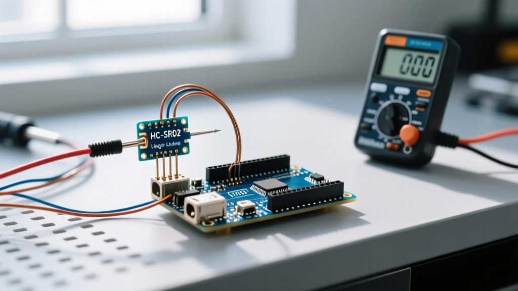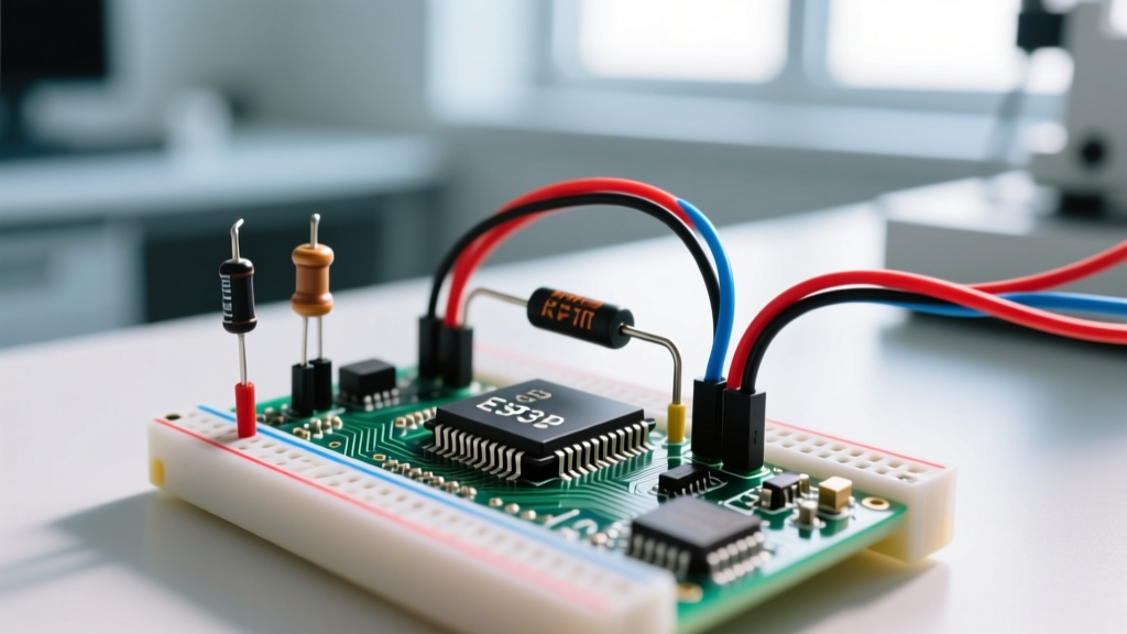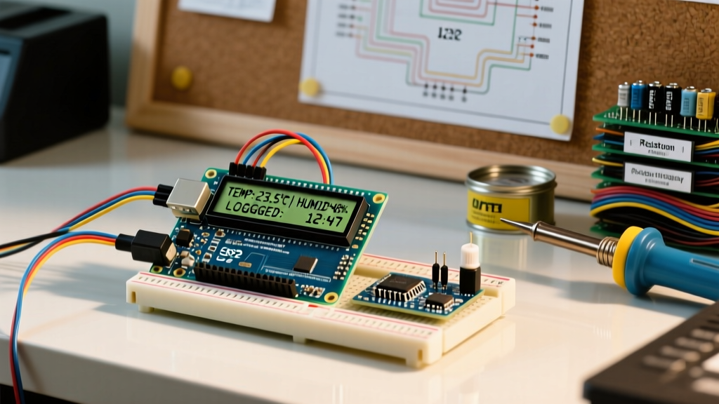

Despite the proliferation of high-resolution OLEDs and full-color TFT screens, the classic 16x2 Arduino LCD remains an undisputed workhorse for industrial monitoring, agricultural sensor hubs, and field-deployable data loggers. Why? Because when you need a display that is readable in direct sunlight, immune to static-image burn-in, and costs less than a cup of coffee, the HD44780-based 16x2 character display is still the optimal engineering choice.
However, moving from a breadboard prototype to a real-world deployment introduces a host of electrical and environmental challenges. Vibration-induced contrast drift, I2C bus noise from switching relays, and ghost characters caused by electromagnetic interference (EMI) can turn a simple display project into a maintenance nightmare. In this guide, we will bypass the basic tutorials and focus on production-grade wiring, hardware hardening, and robust C++ implementation for a multi-sensor environmental monitor.
Why the 16x2 Arduino LCD Still Dominates Field Deployments
Modern makers often default to 0.96-inch I2C OLEDs for sensor readouts. While OLEDs offer superior contrast in dark rooms, they suffer from two critical flaws in real-world applications: poor direct-sunlight visibility and severe pixel burn-in when displaying static 24/7 sensor values (like a constant 'Temp:' label). The standard transflective 16x2 LCD utilizes ambient light to enhance readability outdoors and can run for a decade without burn-in degradation.
Hardware BOM and 2026 Field Pricing
Building a robust sensor node requires more than just the display. Below is a battle-tested Bill of Materials (BOM) for an industrial-grade I2C LCD setup, reflecting current 2026 component pricing.
| Component | Specification / Model | Purpose | Est. Price (2026) |
|---|---|---|---|
| LCD Module | 16x2 HD44780 (Green/Black) | Primary visual output | $2.80 |
| I2C Backpack | PCF8574AT (Address 0x3F) | Reduces GPIO usage to 2 pins | $1.10 |
| Decoupling Cap | 100nF (0.1µF) Ceramic | Filters high-frequency EMI | $0.05 |
| Pull-Up Resistors | 4.7kΩ (1/4W Metal Film) | Stabilizes I2C SDA/SCL lines | $0.10 |
| Fixed Resistor | 1.2kΩ to GND (V0 Pin) | Replaces trimpot for contrast | $0.05 |
Bulletproof I2C Wiring for Noisy Environments
The most common point of failure in DIY sensor hubs is I2C bus corruption. The NXP PCF8574 datasheet specifies that the I2C bus requires proper pull-up resistors to function reliably, especially when wire lengths exceed 10 centimeters or when sharing the bus with high-current sensors.
Step-by-Step Hardened Wiring
- VCC & GND: Connect the backpack VCC to the microcontroller's 5V rail. Crucial: Solder a 100nF ceramic capacitor directly across the VCC and GND pins on the back of the LCD PCB to suppress voltage spikes.
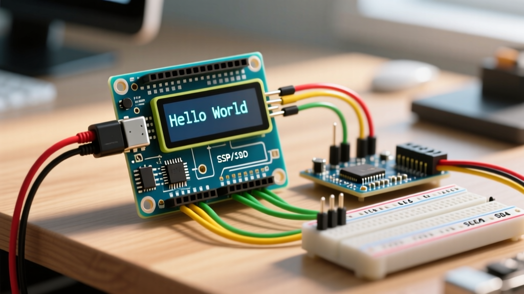
- SDA & SCL: Connect to the hardware I2C pins (A4/A5 on Arduino Uno/Nano, GPIO 21/22 on ESP32).
- Pull-Up Resistors: Solder 4.7kΩ resistors between the SDA and 5V lines, and the SCL and 5V lines. As detailed in the SparkFun Pull-Up Resistor Tutorial, these resistors prevent the lines from floating and ensure sharp signal edges, which is vital when relays switch on and off nearby.
- Wire Selection: Use twisted-pair cable for the I2C lines if the display is mounted more than 30cm away from the microcontroller to minimize inductive coupling from nearby AC mains wiring.
Solving the Contrast Drift Problem
Every standard 16x2 LCD comes with a blue trimpot (potentiometer) on the back to adjust the contrast via the V0 pin (Pin 3). In a lab environment, you tweak it with a screwdriver once and forget it. In a real-world application involving motors, pumps, or vehicular vibration, the mechanical wiper inside the trimpot shifts, causing the display to fade to blank white or turn completely black.
Expert Field Hack: Desolder and discard the factory trimpot. The V0 pin requires a specific voltage drop relative to GND to set the liquid crystal bias. For standard 5V green/blue displays, a fixed 1.2kΩ to 2.2kΩ resistor connected between V0 and GND will permanently lock in perfect contrast, completely eliminating vibration-induced drift.
Production-Ready C++ Implementation
For real-world sensor logging, your code must handle I2C bus lockups gracefully and utilize custom characters to save valuable screen real estate. The following C++ snippet uses the LiquidCrystal_I2C library and includes a custom thermometer icon to maximize the 32-character limit.
#include <Wire.h>
#include <LiquidCrystal_I2C.h>

// Initialize LCD at I2C address 0x3F, 16 columns, 2 rows
LiquidCrystal_I2C lcd(0x3F, 16, 2);

// Custom thermometer character (8x5 pixels)
uint8_t thermometer[8] = {
  0b00100,
  0b01010,
  0b01010,
  0b01010,
  0b01110,
  0b11111,
  0b11111,
  0b01110
};

void setup() {
  Wire.begin();
  // Set I2C clock to 100kHz for better noise immunity over long wires
  Wire.setClock(100000);

  lcd.init();
  lcd.backlight();
  lcd.createChar(0, thermometer);

  lcd.setCursor(0, 0);
  lcd.write(0); // Print custom thermometer
  lcd.print(" Temp: 24.5C");
  lcd.setCursor(0, 1);
  lcd.print(" Hum: 62%  OK");
}

void loop() {
  // Sensor reading logic goes here
  // Always include a watchdog timer in production deployments
}
Troubleshooting EMI and Ghost Characters
When integrating a 16x2 Arduino LCD into a system that controls inductive loads (like water pumps, solenoid valves, or mechanical relays), you will likely encounter 'ghost characters'—random Japanese characters or solid blocks appearing on the screen. This is caused by Back-EMF collapsing into the microcontroller's ground plane, momentarily corrupting the I2C data packet mid-transmission.
EMI Mitigation Matrix
| Symptom | Root Cause | Hardware Solution |
|---|---|---|
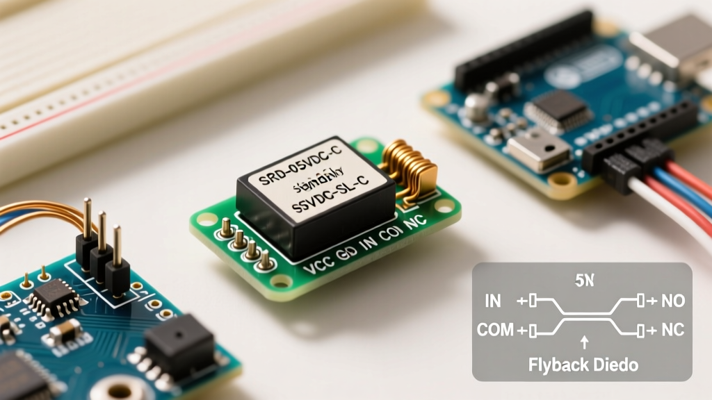
| Random blocks / Japanese text | I2C data corruption via ground bounce | Add 1N4007 flyback diodes across all relay coils; separate logic and power grounds. |
| Display freezes entirely | I2C bus lockup (SDA held low) | Implement a software I2C bus watchdog; use hardware pull-ups (4.7kΩ). |
| Flickering backlight | Insufficient current supply | Power the LCD VCC directly from a dedicated 5V buck converter, not the MCU's linear regulator. |
For a deeper understanding of how the microcontroller handles bus communication and error states, refer to the official Arduino I2C Documentation. By addressing the physical layer weaknesses of the HD44780 and PCF8574 combination, you can transform a $4 hobbyist display into a highly reliable industrial HMI (Human-Machine Interface) capable of surviving harsh environmental deployments.