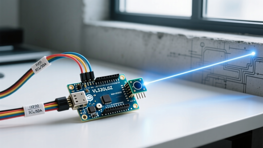

Introduction to Laser Sensor Arduino Integration
Integrating a sensor laser Arduino setup into your DIY electronics project can drastically improve spatial awareness, alignment, and object detection. However, laser peripherals range from simple $1.50 optical pointers to sophisticated $20.00 Time-of-Flight (ToF) LiDAR microchips. When these modules fail, the root cause is rarely the Arduino itself; it usually stems from I2C bus contention, missing current-limiting hardware, or environmental IR interference.
This comprehensive troubleshooting guide dissects the two most common laser modules used in the maker community: the KY-008 Laser Dot Transmitter and the VL53L0X / VL53L1X ToF Distance Sensors. We will explore exact failure modes, circuit-level corrections, and firmware debugging steps to get your project back online.
Part 1: Troubleshooting the KY-008 Laser Dot Module
The KY-008 is a basic 650nm red laser diode module often used for visual alignment or simple optical tripwires. Despite its simplicity, it is frequently destroyed on arrival by beginners due to a critical flaw in its breakout board design.
Failure Mode 1: The Laser is Dim, Flickering, or Dead
The most common reason a KY-008 fails is thermal runaway and overcurrent. The KY-008 breakout board typically includes a small surface-mount resistor, but it is often insufficient for 5V logic. The laser diode has a forward voltage ($V_f$) of approximately 2.8V to 3.2V. If you connect the 'S' (Signal) pin directly to a 5V Arduino Uno digital pin, the excess voltage drives too much current through the diode, causing it to overheat and dim or burn out entirely.
Expert Fix: Never drive a KY-008 directly from a 5V Arduino pin without external current limiting. Calculate the required resistor using Ohm's Law: $R = (V_{source} - V_f) / I$. For a target current of 20mA at 5V: $R = (5V - 3V) / 0.02A = 100\Omega$. Solder a 100Ω 1/4W resistor in series with the 'S' pin. If operating on a 3.3V Arduino (like the ESP32 or Due), a 47Ω resistor is sufficient.
Failure Mode 2: PWM Fading Causes High-Pitched Whining
If you are using analogWrite() to pulse the laser for a visual effect, you may hear a high-pitched whine. This is caused by the piezoelectric effect in the ceramic capacitors on the module or the PWM frequency interacting with the laser diode's junction capacitance. Switch your PWM pin to a higher frequency timer on the Arduino (e.g., using the TimerOne library to push PWM to 20kHz+) to eliminate audible noise.
Part 2: Troubleshooting VL53L0X & VL53L1X ToF Sensors
STMicroelectronics' VL53L0X (and its successor, the VL53L1X) utilizes a 940nm Vertical-Cavity Surface-Emitting Laser (VCSEL) to measure distance via Time-of-Flight. Unlike ultrasonic sensors, ToF is highly precise but highly sensitive to I2C bus health and ambient light. For deeper architectural insights, refer to the official STMicroelectronics VL53L0X Datasheet.
Failure Mode 1: I2C Address Conflicts (Reading 0x00 or Hanging)
Every VL53L0X module ships with the hardcoded default I2C address of 0x29. If you wire two or more sensors to the same Arduino I2C bus, the bus will collide, causing the Wire library to hang or return garbage data. You cannot change the address via software alone on a single active chip; you must use the XSHUT (Shutdown) pin.
- Hardware Wiring: Connect the XSHUT pin of every VL53L0X to a separate, unique Arduino digital output pin. Do not rely on internal pull-ups; use 10kΩ external pull-up resistors to 3.3V on the XSHUT lines for stability.
- Initialization Sequence: Set all XSHUT pins to
LOWto put all sensors in hardware standby. - Address Assignment: Bring Sensor 1 XSHUT
HIGH. It wakes up at0x29. Use the API to change its address to0x30. Bring Sensor 2 XSHUTHIGH, wake it at0x29, and change it to0x31. Repeat for all sensors.
For robust I2C bus management and debugging, consult the Arduino Wire Library Documentation to ensure your pull-up resistor values match your bus capacitance.
Failure Mode 2: Sensor Returns '65535' or '8190' (Timeout Errors)
When using the popular Adafruit or Pololu VL53L0X libraries, a return value of 65535 (or sometimes 8190 depending on the wrapper) indicates a timeout error. The sensor fired the laser but did not receive enough photon bounce-back within the allocated timing budget. This happens for three reasons:
- Target is Out of Range: The VL53L0X maxes out around 2 meters in standard mode. If the target is 3 meters away, it times out.
- Low Reflectivity Target: Aiming the 940nm laser at matte black fabric or Vantablack-style coatings absorbs the IR light. Switch the target to white or grey, or increase the sensor's timing budget.
- Ambient IR Interference: Direct sunlight contains massive amounts of 940nm IR radiation, blinding the sensor's SPAD (Single-Photon Avalanche Diode) array. Fix: Mount the sensor in a shrouded 3D-printed housing with a narrow field-of-view aperture, or switch to a 650nm visible light ToF alternative for outdoor daytime use.
Sensor Comparison & Selection Matrix
Choosing the right laser sensor prevents troubleshooting nightmares before they begin. Below is a 2026 market comparison of popular Arduino-compatible laser peripherals.
| Module | Technology | Wavelength | Max Range | Interface | Avg. Price (2026) |
|---|---|---|---|---|---|
| KY-008 | Optical Pointer | 650nm (Red) | N/A (Visual) | Digital/PWM | $1.50 |
| VL53L0X | ToF LiDAR | 940nm (IR) | 2.0 Meters | I2C | $3.50 (Clone) |
| VL53L1X | ToF LiDAR | 940nm (IR) | 4.0 Meters | I2C | $8.00 |
| TF-Luna | Phase-Shift ToF | 850nm (IR) | 8.0 Meters | UART/I2C | $19.99 |
| Pololu VL53L0X Carrier | ToF LiDAR (Regulated) | 940nm (IR) | 2.0 Meters | I2C | $14.95 |
Why Buy a Premium Carrier Board?
While generic $3.50 VL53L0X breakout boards flood the market, they often lack proper voltage regulation and I2C level shifting. If you are connecting a 3.3V VL53L0X to a 5V Arduino Uno, the I2C SDA/SCL lines will push 5V into the sensor's logic pins, eventually degrading the chip. Premium boards, such as the Pololu VL53L0X Carrier Board, include onboard 3.3V LDO regulators and proper MOSFET-based level shifters, eliminating I2C bus noise and logic-level mismatch errors.
Part 3: Environmental Edge Cases & Optical Physics
Even with perfect wiring, laser sensors can yield erratic data due to the physics of light. Understanding these edge cases is crucial for advanced robotics and automation.
Specular vs. Diffuse Reflection
ToF sensors assume the target will scatter light diffusely back to the receiver lens. If you aim a VL53L0X at a mirror, glass window, or polished metal (specular reflection), the laser beam bounces away at an angle and never returns to the SPAD array. The sensor will report a timeout or a falsely long distance. Solution: Apply a small piece of matte white electrical tape to reflective targets, or angle the sensor slightly off-axis (3 to 5 degrees) so the specular reflection misses the lens, allowing the diffuse scatter to be read.
Temperature Drift in VCSEL Modules
The speed of light is constant, but the internal timing oscillators and the VCSEL junction temperature inside the VL53L0X fluctuate. If your Arduino project is deployed in an unheated garage or an outdoor enclosure where temperatures swing from 0°C to 40°C, you may notice a distance drift of up to 2-3%. The ST API includes a temperature calibration function (vl53l0x_get_temperature()). You must poll the internal temperature sensor and apply the manufacturer's compensation curve in your firmware to maintain millimeter accuracy across thermal extremes.
Summary Checklist for Quick Diagnostics
Before tearing down your circuit, run through this rapid diagnostic checklist:
- KY-008 Dead? Check for a 100Ω current-limiting resistor on 5V logic.
- VL53L0X Not Found on I2C? Run an I2C Scanner sketch. Ensure 4.7kΩ pull-up resistors are present on SDA/SCL.
- Multiple VL53L0X Hanging? Verify XSHUT pins are isolated and initialized sequentially.
- Readings Maxing Out (65535)? Check for ambient sunlight interference, out-of-range targets, or highly absorptive black materials.
- Erratic Jumps? Clean the sensor's glass cover. Fingerprints and smudges cause internal refraction, confusing the ToF histogram algorithms.
By respecting the electrical limits of simple diodes and the optical nuances of Time-of-Flight physics, your sensor laser Arduino projects will achieve industrial-grade reliability in any environment.