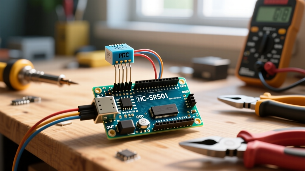

Choosing the Right PIR Module for Your Arduino Project
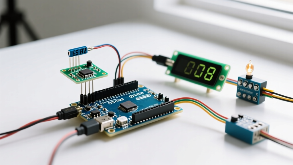
Integrating a motion detector sensor with an Arduino is a foundational skill for home automation, security systems, and interactive art installations. Passive Infrared (PIR) sensors detect changes in infrared radiation, allowing your microcontroller to sense human or animal presence without relying on cameras or wearable tags. However, not all PIR modules are created equal. Selecting the correct sensor depends on your project's spatial constraints, power budget, and required detection range.
Below is a 2026 comparison of the three most common motion detector sensors used in the Arduino ecosystem:
| Module | Core IC / Tech | Detection Range | Avg. Price (2026) | Logic Output | Best Use Case |
|---|---|---|---|---|---|
| HC-SR501 | BISS0001 (Pyroelectric) | Up to 7 meters (120°) | $1.50 - $2.50 | 5V TTL | Room-scale security, lighting control |
| AM312 | Integrated Pyroelectric | Up to 3 meters (100°) | $1.00 - $1.50 | 3.3V / 5V | Compact wearables, battery-powered IoT |
| RCWL-0516 | Microwave Doppler Radar | Up to 9 meters (360°) | $1.80 - $3.00 | 3.3V / 5V | Through-wall detection, outdoor lighting |
For standard indoor motion detector sensor Arduino projects, the HC-SR501 remains the undisputed workhorse due to its adjustable potentiometers and wide detection cone. The AM312 is an excellent alternative if you are designing a low-profile enclosure, as it lacks the bulky potentiometers and the large Fresnel lens dome.
HC-SR501 Pinout and Hardware Wiring
The HC-SR501 operates on the principle of pyroelectricity. The sensor's core IC, the BISS0001, processes the minute analog voltage changes from the pyroelectric element and outputs a clean digital HIGH (3.3V to 5V) when motion is detected. According to the Adafruit PIR Sensor Guide, the module requires a stable DC power supply between 5V and 20V, though 5V is optimal when interfacing directly with a 5V Arduino UNO or Nano.
Wiring Diagram Breakdown
- VCC: Connect to the Arduino 5V pin. Do not use the 3.3V pin on an Arduino UNO, as the HC-SR501 requires at least 4.5V to initialize the internal voltage regulator.
- OUT: Connect to a digital input pin (e.g., Pin 2). This pin goes HIGH (approx. 3.3V to 5V depending on input VCC) when motion is detected.
- GND: Connect to Arduino GND. Ensure a solid ground connection; floating grounds are the primary cause of erratic triggering.
Calibrating the Sensitivity and Delay Potentiometers
One of the main advantages of the HC-SR501 is its hardware-level configurability. The board features two orange trimpots (potentiometers) and a jumper block that dictate the sensor's behavior before the signal ever reaches your Arduino.
1. Delay Time Adjust (Tx)
This potentiometer controls how long the OUT pin stays HIGH after motion is no longer detected. Turning it fully counter-clockwise yields a delay of approximately 0.3 seconds. Turning it fully clockwise extends the delay to roughly 200 seconds (over 3 minutes). For most real-time Arduino applications, setting this to the minimum (0.3s) is recommended, allowing the microcontroller's software to handle the timing logic via code.
2. Sensitivity Adjust (Sx)
This trimpot adjusts both the detection range and the signal amplification. Counter-clockwise reduces the range to about 3 meters, while clockwise pushes it to the maximum 7 meters. If your project is deployed in a small room, lower the sensitivity to prevent the sensor from triggering through drywall or detecting pets in adjacent hallways.
3. Trigger Mode Jumper
The HC-SR501 includes a 3-pin header with a jumper cap. As detailed in the SparkFun PIR Hookup Guide, you can configure the sensor for two modes:
- Non-Retriggerable (L position): The output goes HIGH for the set delay time, then LOW, ignoring any motion during the cooldown phase.
- Retriggerable (H position): The output stays HIGH as long as motion is continuously detected. The delay timer resets with every new movement. This is the default and most useful mode for Arduino integration.
Non-Blocking Arduino Code Implementation
Beginners often use the delay() function to wait for the PIR sensor to reset, which halts the microcontroller and prevents it from reading other sensors or updating displays. Professional firmware relies on non-blocking state machines using the millis() function. This approach is heavily inspired by the official Arduino Debounce Tutorial, adapted here for PIR edge detection.
// Motion Detector Sensor Arduino - Non-Blocking Implementation
const int PIR_PIN = 2;
const int LED_PIN = 13;
const unsigned long ALARM_DURATION = 5000; // 5 seconds

int pirState = LOW;
int lastPirState = LOW;
unsigned long motionDetectedTime = 0;
bool alarmActive = false;

void setup() {
  pinMode(PIR_PIN, INPUT);
  pinMode(LED_PIN, OUTPUT);
  Serial.begin(115200);
  Serial.println('PIR Sensor Initializing...');
  delay(30000); // Mandatory 30s warm-up for BISS0001 thermal stabilization
  Serial.println('Sensor Active.');
}

void loop() {
  int currentPirState = digitalRead(PIR_PIN);
  unsigned long currentMillis = millis();

  // Edge detection: Trigger only on the rising edge (LOW to HIGH)
  if (currentPirState == HIGH && lastPirState == LOW) {
    motionDetectedTime = currentMillis;
    alarmActive = true;
    digitalWrite(LED_PIN, HIGH);
    Serial.println('Motion Detected!');
  }

  // Non-blocking timeout check
  if (alarmActive && (currentMillis - motionDetectedTime >= ALARM_DURATION)) {
    alarmActive = false;
    digitalWrite(LED_PIN, LOW);
    Serial.println('Area Secure.');
  }

  lastPirState = currentPirState;
  // Other non-blocking tasks (e.g., reading temp sensors, Wi-Fi comms) go here
}
This script includes a critical 30-second warm-up period in the setup() block. When first powered, the pyroelectric element and the BISS0001's internal op-amps require time to stabilize their thermal and electrical baselines. Skipping this delay will result in immediate, continuous false triggers upon boot.
Advanced Troubleshooting: Eliminating False Triggers
The most frustrating aspect of integrating a motion detector sensor with an Arduino is dealing with 'ghost' triggers. If your serial monitor registers motion when the room is empty, investigate the following edge cases:
1. Radio Frequency (RF) Interference
The BISS0001 chip is notoriously susceptible to RF noise. If your Arduino project includes an ESP8266, ESP32, or a cellular module, the high-current bursts during Wi-Fi or LTE transmission can couple into the PIR's analog traces, tricking the IC into registering a thermal event. The Fix: Solder a 100µF electrolytic capacitor and a 0.1µF (100nF) ceramic capacitor directly across the VCC and GND pins on the PIR module's PCB. This decouples the power rail and absorbs high-frequency RF spikes.
2. Thermal Drafts and HVAC Vents
PIR sensors do not detect 'people'; they detect changes in infrared heat signatures moving across the zones created by the Fresnel lens. A sudden blast of hot air from an HVAC vent, or even direct sunlight shifting across the floor, will cross these zones and trigger the sensor. The Fix: Use electrical tape to mask off the bottom facets of the Fresnel lens, restricting the detection cone to human torso height and away from floor vents.
3. Power Supply Ripple
Powering the HC-SR501 from a cheap, unregulated 5V USB wall adapter can introduce 50/60Hz AC ripple into the DC line. The BISS0001's internal bandpass filter (tuned to 1Hz–10Hz to match human walking speeds) can sometimes demodulate this ripple as a false signal. The Fix: Power the Arduino and the sensor via a high-quality switching regulator or add an LC low-pass filter on the VCC line.
Pro Tip: If you are mounting the sensor inside a custom 3D-printed enclosure, ensure the plastic is thin enough (under 1.5mm) for the IR wavelengths (8µm to 14µm) to pass through, or use a dedicated cutout for the Fresnel dome. Thick PETG or PLA will block the infrared spectrum entirely, rendering the sensor blind.
By understanding the analog quirks of the BISS0001 chip and utilizing non-blocking Arduino code, you can transform a basic $2 motion detector sensor into a highly reliable, production-grade input device for your next microcontroller project.