
Beyond the Library: Reading the Silicon Truth
When most makers integrate an Arduino LED display into a project, they grab a generic 8x8 dot matrix module, wire it to the SPI or digital pins, and blindly copy-paste a library like LedControl. While this works for basic prototypes, it completely ignores the engineering brilliance—and the hidden pitfalls—of the underlying silicon. To build robust, flicker-free, and power-efficient displays, you must understand the component at a datasheet level.
In this deep dive, we are dissecting the Analog Devices MAX7219/MAX7221 Datasheet. By translating the electrical characteristics, timing diagrams, and application circuits into actionable engineering advice, you will learn how to push your Arduino LED display matrix to its absolute limits while avoiding the catastrophic failure modes that plague amateur builds in 2026.
Inside the Silicon: MAX7219 vs. MAX7221
The market is flooded with modules labeled 'MAX7219', but the datasheet actually covers two distinct chips. Understanding the difference is critical for complex SPI bus architectures.
- MAX7219: The standard driver. When in shutdown mode, its segment and digit drivers go high-impedance, but its serial interface remains active. However, it does not tristate the DOUT pin perfectly in all edge cases, which can cause bus contention if you are sharing the SPI bus with other non-MAX7219 devices.
- MAX7221: The SPI-compliant sibling. It features true high-impedance states on all I/O pins when the chip select (LOAD) is high. If your Arduino LED display shares the hardware SPI bus with an SD card module or an RF transceiver, the datasheet strictly dictates using the MAX7221 to prevent data corruption.
Pinout and Absolute Maximum Ratings
Before wiring your module, we must respect the absolute maximum ratings outlined in Section 2 of the datasheet. Exceeding these will permanently degrade the internal multiplexing logic.
| Datasheet Parameter | Symbol | Min | Typ | Max | Unit |
|---|---|---|---|---|---|
| Supply Voltage | VCC | 4.0 | 5.0 | 5.5 | V |
| Logic High Input | VIH | 3.5 | - | VCC+0.3 | V |
| Logic Low Input | VIL | 0 | - | 1.5 | V |
| Peak Segment Current | ISEG | - | 40 | - | mA |
| Operating Temperature | TA | 0 | - | +70 | °C |
Crucial Note for 3.3V Microcontrollers: If you are driving the display from a 3.3V board (like an ESP32 or Arduino Due), the datasheet specifies a minimum VIH of 3.5V. You must use a logic level shifter on the DIN, CLK, and LOAD lines, or the chip will misinterpret logic highs, resulting in garbage data on the matrix.
The R-SET Resistor: Calculating LED Current
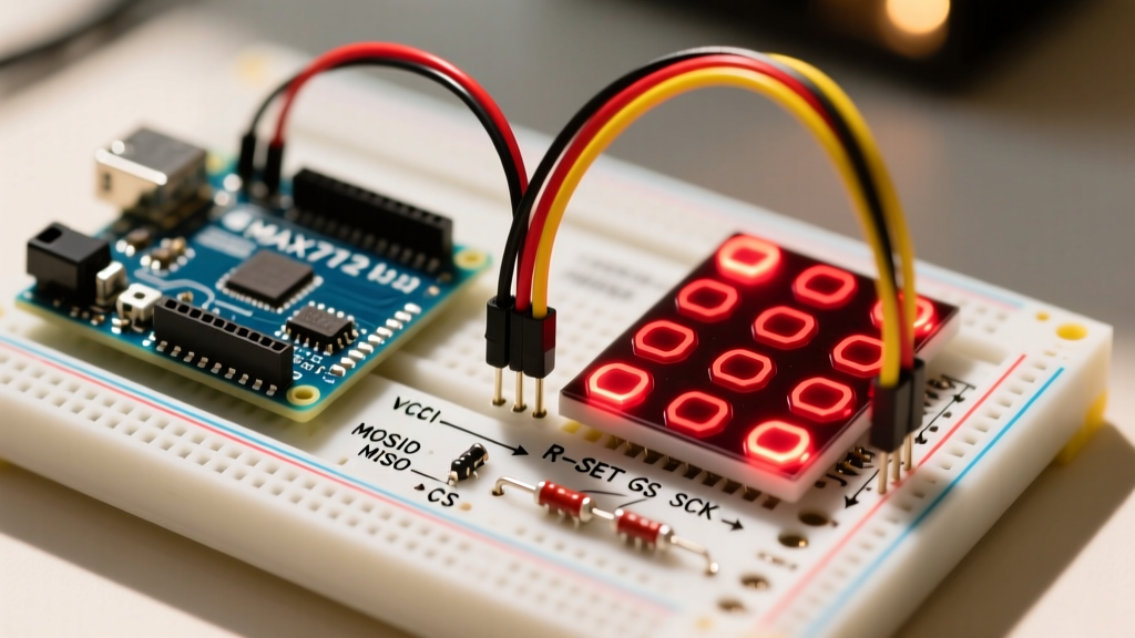
Page 11 of the datasheet contains one of the most misunderstood graphs in hobbyist electronics: the R-SET calculation. Pin 18 (ISET) requires a resistor to ground to program the internal current source. The MAX7219 uses this resistor to set the peak current for the LED segments.
The Calculation Framework
The internal reference voltage is approximately 1.2V. The datasheet provides a formula and a set of curves based on the forward voltage (VF) of your specific LED matrix. For a standard red 8x8 matrix (VF ≈ 2.0V), the formula dictates:
R-SET = (VREF / ISEG) * 100
For a target peak segment current of 40mA: R-SET = (1.2V / 0.040A) * 100 = 3,000 Ohms (3kΩ).
Wait, why do most cheap modules ship with a 10kΩ resistor? Because at 10kΩ, the peak current drops to roughly 12mA. Since the matrix is multiplexed at a 1:8 duty cycle, the average current per LED is a mere 1.5mA. This is a cost-saving and thermal-management measure by module manufacturers. If you want a blindingly bright display for an outdoor installation, you can swap the 10kΩ resistor for a 3.3kΩ resistor, but you must ensure your 5V power supply can handle the resulting 350mA+ total current draw across the module.
Decoding the 16-Bit Serial Protocol
The MAX7219 does not use standard I2C; it uses a proprietary serial interface that mimics SPI. According to the timing diagrams on Page 6, every transmission requires exactly 16 clock cycles.
The Data Packet Structure
- D15-D12 (Don't Care): The chip ignores these bits. We typically send them as zeros.
- D11-D8 (Address): This selects the internal register. Addresses 0x01 through 0x08 correspond to the 8 rows (digits) of the matrix. Addresses 0x09 through 0x0F are control registers.
- D7-D0 (Data): The actual payload. For the matrix, this is the 8-bit bitmask representing which columns (segments) to illuminate in the selected row.
When using the Arduino shiftOut() function, you must send the Address byte first (MSBFIRST), followed by the Data byte. The LOAD (CS) pin must be pulled LOW before the first clock pulse and HIGH immediately after the 16th clock pulse to latch the data into the internal registers.
Daisy-Chaining and the DOUT Pin Delay
One of the most powerful features of the MAX7219 is the ability to daisy-chain multiple modules using the DOUT (Data Out) pin. The datasheet explains that DOUT is simply a buffered mirror of the DIN pin, but it introduces a precise 16.5 clock cycle delay.
This means if you have four 8x8 matrices chained together, you must clock in 64 bits (4 x 16 bits) before raising the LOAD pin. The first 16 bits will ripple through the chain and end up in the 4th module, while the last 16 bits will stay in the 1st module.
The 2026 Counterfeit Chip Problem
When sourcing modules today, be highly vigilant of counterfeit silicon. Many modules sold under the guise of 'MAX7219' actually use clone chips like the MH7219 or unmarked ASICs. While these clones work fine for a single module, the datasheet's precise 16.5 clock cycle delay is often poorly replicated in clones. When daisy-chaining more than three clone modules, the timing skew accumulates, resulting in 'ghosting' (faint illumination of adjacent pixels) and severe flickering. For chains longer than four modules, always source genuine Analog Devices chips or use dedicated hardware SPI with a buffer IC like the 74HC125 to maintain signal integrity over long ribbon cables.
Critical Control Registers Explained
To initialize the Arduino LED display properly, you must configure the internal registers upon boot. Failing to do so leaves the chip in an indeterminate state.
- Shutdown Register (0x0C): Must be set to
0x01for normal operation. On power-up, the chip defaults to shutdown mode to prevent current spikes. - Decode Mode Register (0x09): For a dot matrix, set this to
0x00(No Decode). If you are using a 7-segment display, you would set this to0xFFto enable the internal Code B font decoder. - Intensity Register (0x0A): Accepts values from
0x00(1/32 duty cycle) to0x0F(31/32 duty cycle). Use this for software-based PWM dimming instead of changing the R-SET resistor dynamically. - Scan Limit Register (0x0B): Dictates how many rows are multiplexed. For an 8x8 matrix, set to
0x07(which means scan all 8 rows). Setting this to0x00will only scan one row, making the display appear 8 times brighter but drastically reducing the visible resolution. - Display Test Register (0x0F): Setting this to
0x01turns on all LEDs at maximum current, bypassing all other registers. Use this strictly for manufacturing tests; leaving it on will overheat the chip and degrade the LED epoxy within minutes.
Real-World Troubleshooting & Edge Cases
Even with perfect code, hardware physics can ruin your display. Here are three edge cases derived directly from the application notes in the datasheet:
1. Boot-Up Flicker and Garbage Data
When an Arduino resets, its GPIO pins float before the setup() function initializes them. During this floating state, the MAX7219's CLK and LOAD pins can pick up ambient electromagnetic noise, causing the chip to clock in random garbage data. The Fix: Solder a 10kΩ pull-up resistor between the LOAD (CS) pin and VCC. This ensures the chip ignores all noise while the MCU is booting.
2. The 'Dimming' Effect on Large Chains
If you chain six or more modules, the last module often appears dimmer. The datasheet attributes this to the voltage drop across the thin PCB traces of the VCC and GND lines. The Fix: Do not rely solely on the edge-to-edge pin headers for power. Inject 5V and GND directly into the power terminals of the 3rd and 6th modules in the chain using thick (18 AWG) silicone wire.
3. Hardware SPI vs. Software Bit-Banging
While shiftOut() is fine for a single display, it is far too slow for high-framerate animations. By utilizing the Arduino Hardware SPI library, you can push data at 4MHz or 8MHz. However, the datasheet specifies a maximum CLK frequency of 10MHz. If you route your SPI traces longer than 15cm, the parasitic capacitance of the wires will round off the square wave edges at 10MHz, causing bit-shift errors. Drop the SPI clock divider to 8MHz or 4MHz for long physical runs.
Conclusion
Treating an Arduino LED display as a simple plug-and-play peripheral leaves immense performance and reliability on the table. By respecting the MAX7219 datasheet—specifically the R-SET current calculations, the 16.5-cycle DOUT delay, and the strict initialization register sequence—you transform a fragile hobbyist toy into an industrial-grade visual interface. Whether you are building a multi-meter readout or a scrolling ticker, the silicon truth always dictates the final result.