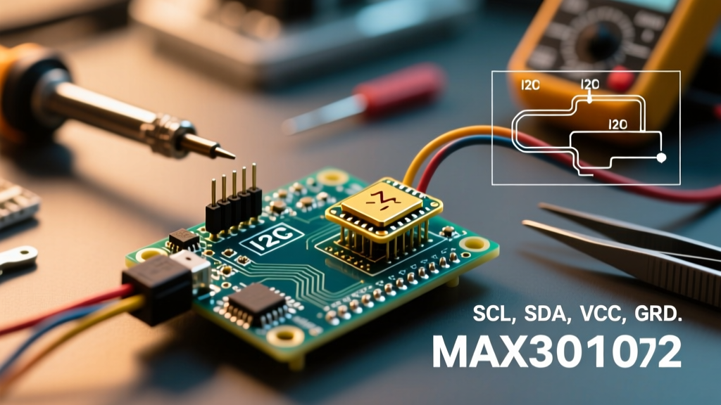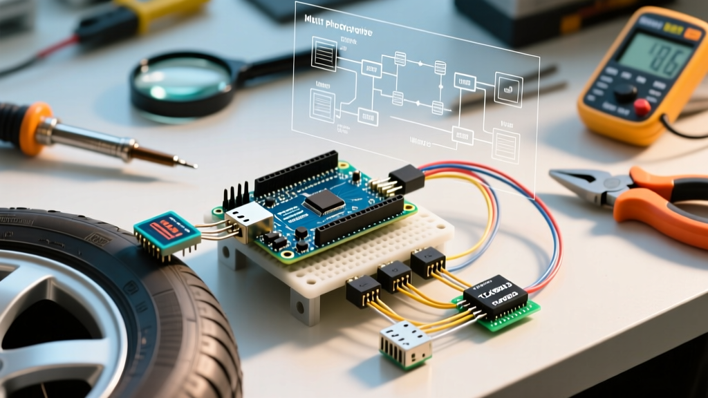

The Engineering Challenge of Rotating Tyre Thermals
For track-day enthusiasts, motorsport engineers, and EV builders, tyre grip is a direct function of the contact patch temperature. While commercial TPMS (Tyre Pressure Monitoring Systems) only measure internal cavity air pressure and ambient temps, a true performance telemetry setup requires surface tread readings. Designing a custom arduino tyre temperature sensor network requires moving beyond basic contact thermistors like the DS18B20, which are impossible to wire to a rotating wheel hub without complex slip rings.
The optimal solution for a multi-peripheral DIY rig is an array of non-contact infrared thermopiles mounted on the suspension uprights, feeding data to a centralized microcontroller alongside an OLED dashboard and an SD card logger. In this 2026 guide, we will engineer a robust, four-wheel telemetry system using the Arduino Uno R4 WiFi, overcoming the inherent I2C bus limitations that cause most beginner builds to fail.
Bill of Materials: 2026 Multi-Peripheral Telemetry Rig
To achieve professional-grade data logging without the $3,000 price tag of commercial motorsport hubs, we are leveraging industrial-grade I2C peripherals. Below is the exact hardware stack required for a four-wheel setup.
| Component | Model / Part Number | Est. Price (2026) | Purpose |
|---|---|---|---|
| Microcontroller | Arduino Uno R4 WiFi | $27.50 | Core processing, WiFi telemetry, 5V logic |
| IR Thermopile (x4) | Melexis MLX90614 BAA (35° FOV) | $56.00 ($14 ea) | Non-contact tread temperature measurement |
| I2C Multiplexer | NXP TCA9548A Breakout | $4.50 | Resolves I2C address collisions |
| Display | SSD1306 128x64 OLED (I2C) | $6.00 | In-cabin real-time driver dashboard |
| Data Logging | Adafruit MicroSD Breakout (SPI) | $7.99 | High-speed CSV telemetry logging |
Total Hardware Cost: ~$101.99 (excluding wiring, 3D printing filament, and suspension mounting brackets).
Overcoming the I2C Address Collision (The TCA9548A Solution)
The most common failure point when building an arduino tyre temperature sensor array is the I2C address collision. The Melexis MLX90614 is an incredible digital plug-play infrared thermometer, but it ships with a hardcoded default I2C address of 0x5A. While it is possible to reprogram the EEPROM of each sensor to have a unique address, doing so requires a risky one-time programming sequence that can permanently brick the sensor if voltage spikes occur.
The professional workaround is to use the NXP TCA9548A I2C multiplexer. This chip acts as a digital switchboard, allowing you to connect up to 8 separate I2C buses to a single Arduino SDA/SCL line.
Wiring the Multiplexer Matrix
- Arduino Uno R4 SDA/SCL: Connect to the TCA9548A primary SDA/SCL pins.
- TCA9548A Channels 0-3: Route to the four MLX90614 sensors (Front Left, Front Right, Rear Left, Rear Right).
- TCA9548A Channel 4: Route to the SSD1306 OLED Display.
- Decoupling Capacitors: Solder a 10µF ceramic capacitor across the VCC and GND pins of each MLX90614 sensor. Long wire runs through a vehicle chassis introduce severe EMI (Electromagnetic Interference) from the alternator and ignition coils, which will corrupt I2C packets without local decoupling.
Sensor Calibration: Emissivity and Field of View
Out of the box, the MLX90614 is calibrated for an emissivity of 1.0 (a perfect blackbody). However, vulcanized rubber tyre compounds have an actual emissivity of approximately 0.95. If you do not compensate for this, your Arduino will report temperatures that are 2°C to 4°C lower than reality—a massive margin of error when tuning tyre pressures for a track day.
Expert Calibration Step: You must write the 0.95 emissivity coefficient to the EEPROM of each sensor. Using theWire.hlibrary, send the unlock command0x2Dto the EEPROM address0x05, calculate the hex equivalent of 0.95 (which is0xF23D), write it, and power cycle the sensor. Do this for all four sensors before installing them on the vehicle.
Managing the 35° Field of View (FOV)
The 'BAA' variant of the MLX90614 features a 35-degree FOV. If mounted too far from the tyre, the sensor's vision cone will overlap with the hot brake rotor or the cooler wheel barrel, resulting in an averaged, inaccurate reading.
The Fix: 3D print a mounting shroud using ASA or PETG filament (PLA will melt under track-day brake heat). The shroud should feature a narrow internal baffle that restricts the sensor's vision strictly to the tyre sidewall and outer tread shoulder, positioned exactly 40mm to 60mm away from the rubber.
Data Logging and OLED Dashboard Integration
With the sensors reading accurately, the multi-peripheral setup must process and store the data without blocking the main Arduino loop. Reading four sensors, updating an SPI SD card, and refreshing an I2C OLED can easily push loop times past 100ms, causing data gaps during high-speed cornering.
Handling SD Card Write Latency
Standard SD card libraries (SD.h) block the microcontroller while writing to the FAT32 file system. To maintain a strict 50Hz (20ms) telemetry sampling rate, you must implement a ring buffer in the Arduino's SRAM.
- Create a char array buffer of 2048 bytes.
- Append CSV formatted strings (Timestamp, FL, FR, RL, RR, Ambient) to the buffer during each loop iteration.
- Only trigger the
file.write()andfile.flush()commands when the buffer reaches 1800 bytes. - This reduces SD card write operations from 50 times a second to roughly once every second, eliminating SPI bus bottlenecks and preventing missed I2C sensor polls.
Real-World Track Failure Modes and Troubleshooting
When deploying this arduino tyre temperature sensor rig in a real vehicle, environmental factors will attempt to destroy your data integrity. Here is how to troubleshoot the most common edge cases:
- Brake Rotor IR Bleed: If your Front Left sensor suddenly spikes to 180°C during braking, your 3D-printed shroud is too short, and the thermopile is catching the edge of the cast-iron brake rotor. Extend the shroud baffle by 15mm and angle the sensor 5° downward toward the contact patch.
- I2C Bus Timeout at High RPM: If the Arduino freezes when the engine crosses 5,000 RPM, alternator EMI is collapsing the I2C pull-up voltage. Replace the standard 4.7kΩ I2C pull-up resistors on the TCA9548A board with stronger 2.2kΩ resistors to stiffen the bus against electrical noise.
- Water Ingress / Track Day Rain: The MLX90614 TO-39 can is not waterproof. A single drop of water on the infrared lens will refract the thermal reading, causing it to drop to ambient water temperature. Seal the sensor lens with a piece of high-transmission IR Kapton tape and pot the rear PCB connections in marine-grade epoxy.
Understanding Tyre Thermal Gradients
According to Tire Rack's technical guidelines on tyre temperatures, measuring the surface temperature is only half the battle; understanding the gradient across the tread is what dictates camber and pressure adjustments. While this guide focuses on a single-point shoulder reading per wheel, the architecture provided (using the TCA9548A) leaves you with 4 open I2C channels.
For advanced 2026 builds, motorsport engineers often expand this multi-peripheral setup by adding three MLX90614 sensors per wheel (Inside Shoulder, Center Tread, Outside Shoulder) to calculate a live thermal camber map, pushing the total sensor count to 12. The Arduino Uno R4 WiFi's 32-bit ARM Cortex-M4 processor handles this mathematical load effortlessly, allowing you to transmit the thermal deltas via UDP to a pit-lane laptop in real-time.
Summary
Building a reliable, multi-peripheral arduino tyre temperature sensor telemetry rig requires respecting the physics of infrared thermodynamics and the electrical realities of automotive environments. By utilizing the MLX90614 thermopiles, bypassing address collisions with the TCA9548A multiplexer, and buffering your SD card writes, you can achieve professional-grade track data for under $110. Ensure your 3D-printed mounts are heat-resistant, your emissivity is calibrated to 0.95, and your I2C bus is protected from alternator whine. Safe tuning, and see you at the apex.