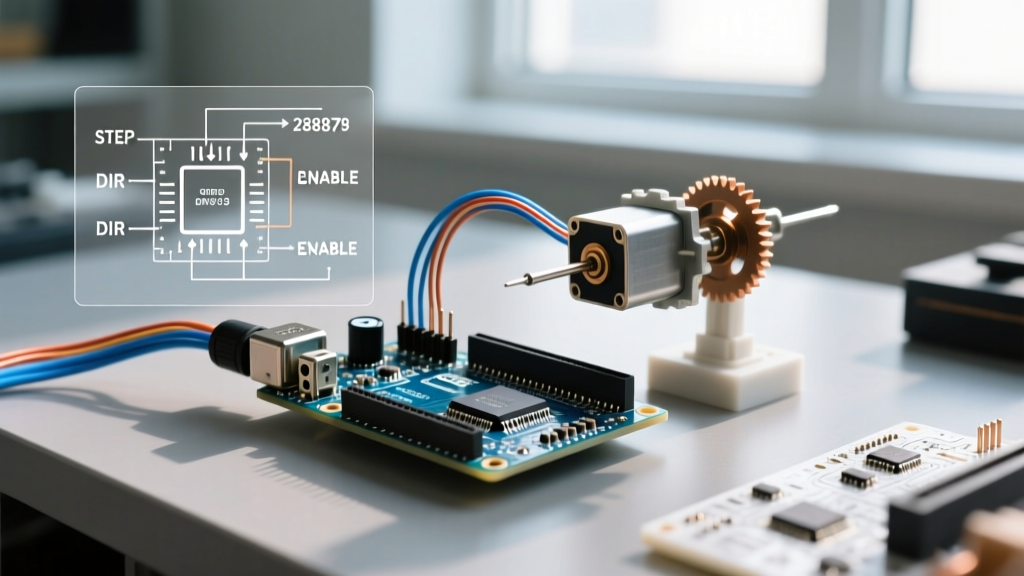

Beyond the Tutorial: Why the DRV8825 Datasheet Matters
When makers and engineers begin their journey into arduino stepper motor control, the DRV8825 stepper driver carrier (typically priced between $4.50 and $6.50 in 2026) is the undisputed workhorse of the DIY CNC and 3D printing world. Capable of driving bipolar stepper motors up to 2.5A per phase with 1/32 microstepping, it is a massive upgrade over the older A4988. However, blindly copying wiring diagrams and Arduino sketch templates without consulting the actual silicon datasheet is the leading cause of melted driver boards, missed steps, and acoustic motor screaming. This guide dissects the Texas Instruments DRV8825 datasheet, translating its dense engineering specifications into actionable, real-world parameters for your microcontroller projects.
Deconstructing the Block Diagram: The Translator and Indexer
The DRV8825 is not just a simple H-bridge; it is a complete motor control system on a single QFN package. The datasheet's block diagram reveals three critical subsystems that dictate how your Arduino's digital pulses translate into physical motion:
- The Charge Pump: This internal circuitry generates the high-side gate drive voltages for the N-channel MOSFETs. The datasheet explicitly states that the VMOT (Motor Voltage) pin must be between 8.2V and 45V. If you attempt to power a 12V stepper motor with a 5V VMOT supply, the charge pump will fail to activate the high-side FETs, resulting in a dead motor and potential chip damage.
- The Indexer: This is the brain of the microstepping operation. It takes your basic STEP and DIR signals and generates the complex sine/cosine current waveforms required for smooth rotor movement.
- The Translator (Control Logic): This handles the MODE0, MODE1, and MODE2 pins, dictating the step resolution table that the indexer will follow.
The Microstepping Truth Table: Resolution vs. Reality
One of the most misunderstood sections of the datasheet is the microstepping configuration table. While the DRV8825 supports up to 1/32 step resolution, higher resolution is not universally better. Pushing a 16MHz Arduino Uno to generate the massive pulse trains required for 1/32 microstepping at high RPMs often leads to timer overflows and jitter.
| MODE0 | MODE1 | MODE2 | Microstep Resolution | Steps per Revolution (1.8° Motor) | Recommended Use Case |
|---|---|---|---|---|---|
| Low | Low | Low | Full Step | 200 | High-speed, low-torque conveyors |
| High | Low | Low | 1/2 Step | 400 | Basic robotics, low-cost CNC |
| Low | High | Low | 1/4 Step | 800 | Standard 3D printer axes |
| High | High | Low | 1/8 Step | 1600 | Precision laser engravers |
| Low | Low | High | 1/16 Step | 3200 | High-resolution camera sliders |
| High | High | High | 1/32 Step | 6400 | Ultra-quiet, low-speed optics |
Datasheet Insight: At 1/16 and 1/32 stepping, the indexer relies on highly precise internal DACs. If your Arduino's STEP pin wiring is long and unshielded, electromagnetic interference (EMI) from the motor coils can induce false step pulses, causing the motor to drift over time. Keep STEP/DIR wires under 10cm or use twisted pairs.
Current Limiting Mathematics: Calculating VREF
Setting the current limit is where 90% of beginners destroy their hardware. The datasheet defines the trip current ($I_{CHOP}$) based on the voltage at the REF pin and the value of the sense resistors ($R_S$).
Critical Distinction: The formula for the DRV8825 is fundamentally different from the A4988. Do not use A4988 calculators for this chip.
For standard carrier boards (like the Pololu #2133 or reputable 2026 clones) utilizing 0.100Ω sense resistors, the mathematical relationship derived from the datasheet's internal gain structure simplifies to:
Current Limit = VREF × 2
Example Calculation: You are driving a standard NEMA 17 stepper motor rated for 1.5A per phase. However, stepper motor current ratings are typically peak, not continuous RMS. To prevent thermal saturation, you should target 70% to 80% of the rated max. Let's target 1.2A continuous.
- Target Current = 1.2A
- VREF = Target Current / 2
- VREF = 1.2 / 2 = 0.60V
Using a digital multimeter, probe the metal shaft of the onboard potentiometer against a system ground while the logic (VDD) is powered. Adjust the pot until you read exactly 0.60V. Warning: Never use a metal screwdriver to adjust the pot while the board is powered; the shaft is electrically connected to the wiper and can short to adjacent pins.
Decay Modes: Solving the Mid-Band Resonance Problem
Stepper motors operate by rapidly charging and discharging inductive coils. The rate at which the current decays when the H-bridge turns off is critical. The DRV8825 datasheet details three decay modes: Fast, Slow, and Mixed.
- Slow Decay: Recirculates current through the low-side FETs. Excellent for smooth low-speed microstepping but causes severe current ripple at high speeds.
- Fast Decay: Reverses the voltage across the coil to drop current rapidly. Prevents high-speed ripple but introduces massive acoustic noise and vibration at low speeds.
- Mixed Decay: The DRV8825's indexer automatically blends fast and slow decay based on the microstep position. This is crucial for avoiding "mid-band resonance"—a phenomenon where the motor violently vibrates and stalls between 10 and 20 RPM. If your motor "sings" or stalls at low speeds, ensure you are not accidentally forcing a decay mode via external circuit modifications.
Step and Direction Timing Constraints
Microcontrollers like the ESP32 or Arduino Due can toggle GPIO pins in nanoseconds, but the DRV8825 silicon has physical propagation delays. The datasheet specifies a minimum STEP pulse width ($t_{WH(STEP)}$) of 1.9 µs and a minimum STEP pulse low time ($t_{WL(STEP)}$) of 1.9 µs.
If your Arduino code uses direct port manipulation that toggles the pin faster than 3.8 µs per full cycle, the DRV8825's indexer will completely ignore the pulses. Always insert a minimum 2-microsecond delay in your step-generation routines to guarantee the silicon registers the command.
The "Silent Killer": VMOT Capacitors and Breadboard Limits
Page 14 of the TI datasheet contains a warning that is frequently ignored: "A 100-µF or larger electrolytic capacitor must be placed between VMOT and GND."
Stepper motor coils are highly inductive. When the H-bridge abruptly cuts power to a coil during a microstep transition, the collapsing magnetic field generates a massive voltage spike (inductive kickback). The bulk capacitor absorbs this spike. Without it, the spike exceeds the 45V absolute maximum rating of the VMOT pin, instantly puncturing the internal MOSFET gate oxides. The driver will short VMOT to ground and permanently die.
Furthermore, the datasheet's thermal layout section emphasizes the importance of the exposed thermal pad on the bottom of the QFN package. On carrier boards, this is soldered to the ground plane to dissipate heat. If you plug the carrier into a standard solderless breadboard, the thermal resistance increases drastically. Testing shows that at 1.5A on a breadboard without a heatsink, the DRV8825 will hit its 165°C thermal shutdown threshold in under 45 seconds. For continuous operation above 1.0A, solder the carrier to a PCB with a ground pour or attach an active cooling fan.
Diagnostic Matrix: Datasheet-Backed Troubleshooting
When your arduino stepper motor control circuit fails, use this matrix derived directly from the datasheet's fault-protection logic to diagnose the issue.
| Observed Symptom | Datasheet Root Cause | Actionable Fix |
|---|---|---|
| Motor vibrates loudly but shaft does not rotate. | STEP pulse width < 1.9µs, or VREF set below the motor's holding torque threshold. | Verify code timing delays; increase VREF by 0.1V increments. |
| Driver becomes untouchably hot and stops moving intermittently. | Thermal Shutdown (TSD) triggered at 165°C due to inadequate copper pour or airflow. | Move off breadboard; solder to perfboard with ground plane; add 40mm fan. |
| Motor moves in full steps despite MODE pins being set to 1/16. | MODE pin logic levels are floating or not meeting the 2V VIH threshold. | Add 10kΩ pull-down resistors to MODE pins; ensure solid GND connection. |
| Driver emits a pop and smells like ozone upon first power-up. | Missing VMOT bulk capacitor caused inductive spike to breach 45V max rating. | Replace driver; solder 100µF+ electrolytic capacitor directly to VMOT/GND header pins. |
Authoritative Sources & Further Reading
- Texas Instruments DRV8825 Product Page & Official Datasheet - The definitive source for timing diagrams, absolute maximum ratings, and thermal resistance metrics.
- Pololu DRV8825 Stepper Motor Driver Carrier Documentation - Essential reference for carrier-specific VREF calculations, sense resistor values, and wiring schematics.