
The Challenge of Infrared Sensor Arduino Multi-Peripheral Setups
Integrating an infrared sensor Arduino configuration into a broader multi-peripheral system is a rite of passage for embedded engineers. While reading a 38kHz IR receiver like the Vishay TSOP4838 is trivial in isolation, combining it with an I2C OLED display and a high-torque servo motor introduces severe architectural bottlenecks. In 2026, with the industry standard shifting toward the Arduino Uno R4 Minima and ESP32-C3 ecosystems, legacy timer conflicts have evolved into complex DMA and interrupt priority clashes.
This guide dissects the exact hardware, power budgeting, and software architecture required to run an IR remote decoder, a 128x64 I2C OLED, and an MG996R servo simultaneously without dropping keypresses or inducing servo jitter.
Hardware Bill of Materials and Power Budgeting
A common failure point in multi-peripheral setups is inadequate power delivery. The Arduino onboard 5V regulator cannot simultaneously supply an I2C display and a high-torque servo. Below is the precise 2026 BOM for a robust smart-access control prototype.
| Component | Model / Specification | Est. Price (2026) | Peak Current Draw |
|---|---|---|---|
| Microcontroller | Arduino Uno R4 Minima (Renesas RA4M1) | $22.00 | 45 mA |
| IR Receiver | Vishay TSOP4838 (38kHz) | $1.45 | 5 mA |
| Display | SSD1306 0.96" I2C OLED (128x64) | $6.50 | 20 mA |
| Actuator | MG996R Metal Gear Servo | $8.50 | 2.5A (Stall) |
| Power Stage | LM2596 Buck Converter (5V Output) | $2.50 | N/A |
The 'Ghost Signal' Problem: Power Sag and Decoupling
Before writing a single line of code, you must address the physical layer. The MG996R servo can draw up to 2.5A during stall conditions. Even with an external LM2596 buck converter, the transient current spikes cause high-frequency noise on the shared ground plane. This noise couples into the TSOP4838 data line, causing the IRremote library to register phantom NEC protocol commands.
The Mandatory Decoupling Network
According to the Adafruit IR Sensor Guide, bare IR modules are highly susceptible to power supply ripple. To eliminate ghost signals in a multi-peripheral setup, you must implement the following analog filtering directly at the IR receiver pins:
- 100Ω Series Resistor: Place this between the 5V rail and the TSOP4838 VCC pin to isolate it from systemic voltage sags.
- 10µF Ceramic Capacitor: Solder this directly across the VCC and GND pins of the IR receiver to act as a local energy reservoir.
- 4.7kΩ Pull-up Resistor: Connect between the data out pin and 5V to ensure clean logic-high transitions, preventing floating states during I2C bus congestion.
The Root Cause: Interrupt Latency and Timer Collisions
On legacy AVR boards (like the Uno R3), the Servo.h library monopolizes Timer1 to generate the 50Hz PWM signal. Simultaneously, the IRremote library requires a hardware timer to sample the receiver pin every 50µs. If both attempt to claim Timer1, the compiler throws a conflict, or worse, the servo twitches violently as the IR interrupt preempts the PWM pulse width calculation.
While the modern Arduino Uno R4 Minima utilizes a 32-bit Renesas RA4M1 core with a more flexible timer array, the abstraction layers in standard Arduino libraries still cause interrupt latency. Furthermore, updating an I2C OLED display via the Adafruit_SSD1306 library can block the main execution loop for up to 15ms. If a 38kHz IR burst arrives during this I2C blocking window, the hardware timer interrupt may be delayed, corrupting the protocol decoding and resulting in a dropped keypress.
Expert Insight: Never use blocking delays (delay()) or synchronous I2C screen updates in the main loop when decoding IR signals. The IR buffer will overflow in milliseconds, leading to unresponsive remote controls.
Optimized Pin Allocation Strategy
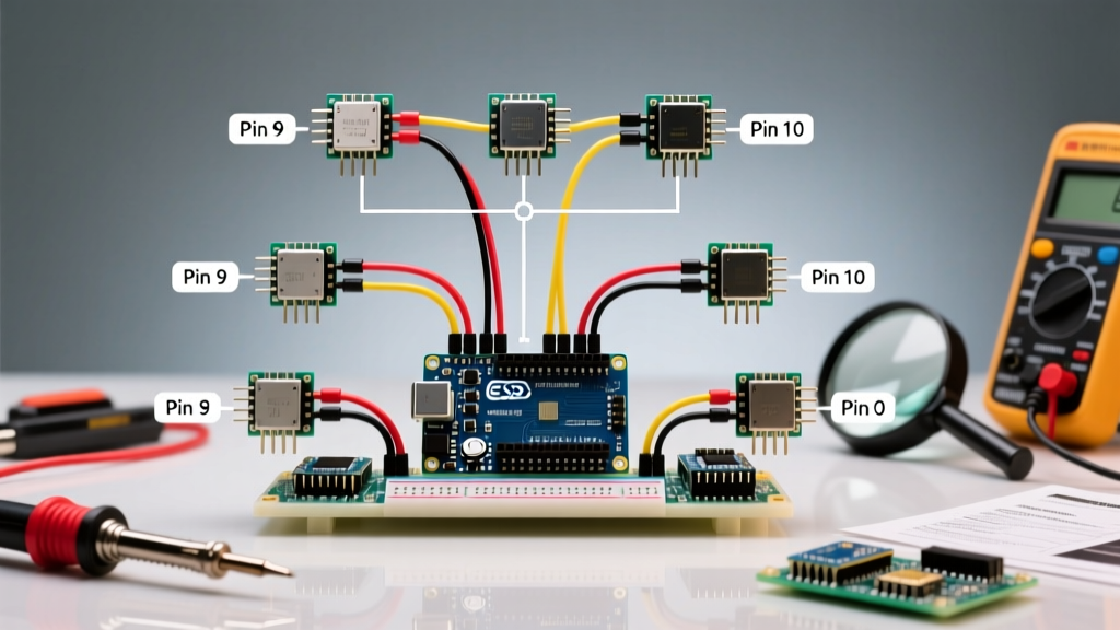
To avoid hardware peripheral overlap on the Uno R4 Minima, map your components to dedicated, non-conflicting pins. Avoid using pins tied to the primary I2C or SPI buses for your IR input.
- IR Receiver Data Pin: Digital Pin 2 (Supports external hardware interrupts INT0, ensuring immediate wake-up on signal edge).
- I2C OLED SDA/SCL: Default I2C pins (SDA on A4, SCL on A5 for legacy compatibility, or dedicated R4 I2C headers).
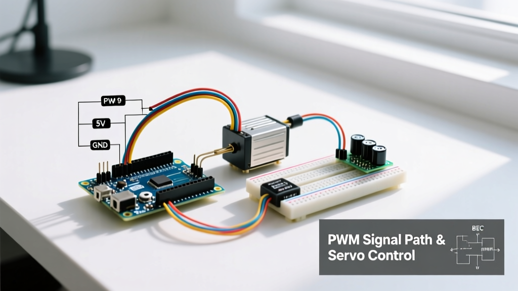
- Servo PWM Pin: Digital Pin 9 (Routes to a dedicated 16-bit timer on the RA4M1 for jitter-free 50Hz generation).
Software Architecture: Non-Blocking IR Decoding
To achieve a seamless infrared sensor Arduino multi-peripheral setup, you must utilize the latest v4.x architecture of the Arduino-IRremote GitHub Repository. The modern library allows you to offload sampling to Pin Change Interrupts (PCINT) or alternate hardware timers, freeing up resources for the Servo and I2C buses.
Handling I2C Clock Stretching and Display Lag
Instead of redrawing the entire OLED buffer every loop iteration, use a state-change flag. Only update the display when a new, valid IR command is decoded and verified. This reduces I2C bus occupation from 15ms per loop to roughly 15ms per keypress, entirely eliminating the risk of IR buffer overflow.
Furthermore, leverage the Arduino Interrupt Documentation to understand how to keep your Interrupt Service Routines (ISRs) lean. The IR decoding should happen in the background via the library's timer ISR; your main loop should only call IrReceiver.decode() and parse the result.
Troubleshooting Edge Cases in the Field
1. Sunlight and Ambient IR Noise
The TSOP4838 features an automatic gain control (AGC) circuit designed to suppress continuous 38kHz noise (like CFL bulbs). However, direct sunlight contains massive broadband infrared radiation that can saturate the photodiode, effectively blinding the sensor. If your multi-peripheral setup is deployed outdoors or near a window, you must install a physical daylight-blocking optical filter (often a dark red acrylic shield) over the receiver dome, or switch to a specialized high-ambient-light sensor like the Vishay TSOP57338.
2. Servo Jitter During IR Decoding
If your MG996R servo twitches precisely when you press a button on the remote, you are experiencing interrupt priority inversion. The IR sampling ISR is taking too long to execute, delaying the servo PWM timer interrupt. Ensure you are using the IRrecv class rather than the blocking IRrecvDump examples, and verify that your external 5V buck converter shares a common ground with the Arduino GND pin to prevent ground-loop induced PWM jitter.
Summary
Building a reliable infrared sensor Arduino system alongside motors and displays requires moving beyond basic tutorial code. By implementing proper analog decoupling, respecting I2C bus timing constraints, and leveraging modern interrupt-driven library architectures, you can eliminate timer clashes and build industrial-grade multi-peripheral prototypes.