
The Challenge of Multi-Node Ultrasonic Arrays
Integrating a single distance sensor into a microcontroller project is a foundational rite of passage. However, scaling up to a multi-peripheral setup—such as a 360-degree collision avoidance rover or a liquid level monitoring array—introduces severe hardware and acoustic challenges. When building a multi-node ultrasonic arduino system, engineers frequently encounter ghost echoes, I/O pin exhaustion, and severe power rail brownouts. As of 2026, with the widespread adoption of the 5V-tolerant Arduino Uno R4 Minima ($22.00) and advanced 3D-printed acoustic shrouds, achieving reliable multi-sensor arrays is highly feasible, provided you respect the physics of sound and the electrical limits of your power delivery network.
The Physics of Acoustic Crosstalk
The most common failure mode in multi-sensor setups is acoustic crosstalk. Standard 40kHz ultrasonic transducers emit a sound cone with an effective beam angle of roughly 30 degrees. If you fire two sensors simultaneously, or even in rapid succession, Sensor B's receiver will detect the echo from Sensor A's transmitter bouncing off a distant wall. The microcontroller interprets this as a localized obstacle, resulting in erratic 'ghost' readings.
'In robotic navigation, multipath reflections and transducer crosstalk are the primary culprits behind phantom obstacle detection. Sequential polling with adequate settling time is non-negotiable for 40kHz arrays.' — Principles of Autonomous Mobile Robotics
To eliminate this, you must calculate the maximum time-of-flight (ToF) for your environment. Sound travels at approximately 343 meters per second at 20°C. For a maximum detection range of 4 meters, the round-trip distance is 8 meters. Dividing 8 meters by 343 m/s yields a travel time of roughly 23.3 milliseconds. Adding a 10ms acoustic settling buffer to allow residual reverberations to dissipate, you must enforce a strict minimum delay of 35ms between firing adjacent sensors.
Sensor Selection Matrix for Multi-Node Arrays
Not all transducers are suited for dense arrays. Selecting the correct module dictates your wiring topology and power budget. Below is a comparison of the three most common modules used in Arduino ecosystems today.
| Module | Max Range | Blind Zone | Peak Current | Price (2026) | Best Use Case |
|---|---|---|---|---|---|
| HC-SR04 | 400 cm | 2 cm | ~15 mA | $1.20 - $1.80 | Indoor robotics, dry environments |
| JSN-SR04T (v3.0) | 450 cm | 20 cm | ~250 mA | $4.50 - $6.00 | Automotive, outdoor, liquid tanks |
| RCWL-1601 | 300 cm | 2 cm | ~12 mA | $1.80 - $2.20 | 3.3V logic boards (ESP32/RP2040) |
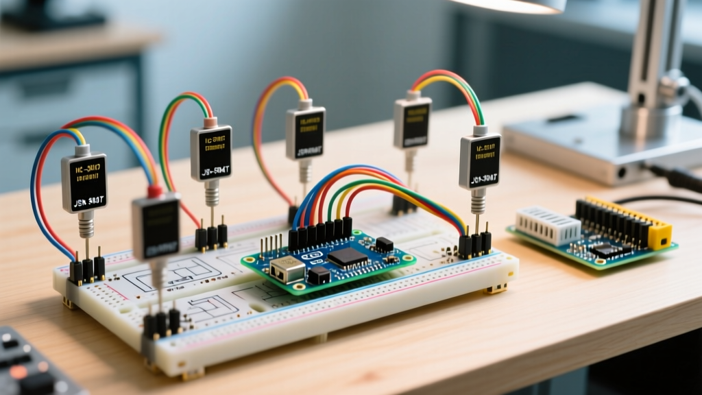
For a robust multi-peripheral setup, the JSN-SR04T is often preferred due to its waterproof IP67 transducer head, which physically separates the transmitter and receiver, reducing near-field acoustic bleed. However, its massive peak current draw introduces severe power delivery challenges.
Power Delivery: Preventing the 40kHz Brownout
A critical, often overlooked aspect of ultrasonic arrays is instantaneous current draw. When a JSN-SR04T fires its 40kHz burst, it draws up to 250mA for a fraction of a millisecond. If your Arduino is polling four sensors in rapid sequence, or if decoupling is inadequate, the cumulative inrush current can cause the 5V rail to sag below 4.2V. This triggers a brownout reset on the ATmega or Renesas RA4M1 microcontroller, or causes the sensor's internal comparator to latch up, returning a permanent '0cm' error.
The LM2596 Buck Converter Injection Method
Do not power a multi-sensor array directly from the Arduino's onboard 5V linear regulator or a standard USB port (limited to 500mA). Instead, use a dedicated LM2596 buck converter fed by a 12V LiPo battery pack, dialed precisely to 5.1V. Wire the 5V output directly to the VCC pins of all ultrasonic sensors. Crucially, you must solder a 220µF electrolytic capacitor and a 100nF ceramic capacitor in parallel across the VCC and GND pins of each individual sensor. This local energy reservoir supplies the 250mA inrush demand without pulling down the main voltage rail.
Temperature Compensation for Precision Arrays
In multi-sensor setups used for volumetric calculations (like water tank level monitoring), ignoring ambient temperature will introduce severe errors. The speed of sound is not a static constant; it fluctuates with air temperature according to the formula: v = 331.3 + (0.606 * T), where T is temperature in Celsius.
If your array is calibrated for 20°C (343.4 m/s) but operates in a 35°C environment (352.5 m/s), a true distance of 300cm will be miscalculated by the Arduino as 308cm. To maintain precision across a multi-peripheral network, integrate a single BME280 I2C environmental sensor on the array. Read the temperature once per polling loop, dynamically update the microseconds-per-centimeter divisor in your firmware, and apply the corrected scalar to all four ultrasonic echo returns.
Pin Topologies and the Blocking pulseIn() Trap
The native Arduino function pulseIn() is fundamentally flawed for multi-sensor arrays. It is a 'blocking' function, meaning the microcontroller halts all other operations (including motor PWM control and serial communication) while waiting for an echo to return. If a sensor faces an open void and times out at the default 1000ms, your entire robotic system freezes for a full second.
According to the Arduino Uno R4 Minima Cheat Sheet, modern boards possess hardware timers that should be leveraged for non-blocking operations. Instead of pulseIn(), utilize timer interrupts or the highly optimized NewPing library. NewPing utilizes hardware timers to measure the echo pulse width in the background, freeing the main loop to handle navigation logic, servo actuation, and telemetry streaming simultaneously.
Sequential Polling Architecture
Wire your array using dedicated Trigger and Echo pins for each node to avoid complex analog multiplexing (like the CD4051B), which can degrade the fast rising edges of the 5V echo pulse. A standard 4-sensor setup requires 8 digital I/O pins. The software polling sequence must strictly follow this loop:
- Set Sensor 1 Trigger HIGH for 10µs.
- Listen for Sensor 1 Echo via interrupt.
- Wait 35ms (Acoustic Settling Time).
- Set Sensor 2 Trigger HIGH for 10µs.
- Listen for Sensor 2 Echo via interrupt.
- Repeat for Sensors 3 and 4.
Physical Beam Collimation Techniques
Software timing cannot fix physical acoustic overlap if sensors are mounted too closely on a chassis. The SparkFun Selection Guide for Distance Sensors notes that bare transducers suffer from massive side-lobe reflections. To narrow the beam angle from 30 degrees down to a tight 12-degree corridor, design and 3D-print acoustic shrouds using TPU (Thermoplastic Polyurethane) filament. TPU's inherent flexibility and density absorb off-axis 40kHz vibrations far better than rigid PLA or ABS. Line the interior of the shroud with open-cell acoustic foam to eliminate internal standing waves, ensuring the receiver only captures direct, on-axis reflections.
Troubleshooting Edge Cases and Failure Modes
When deploying your multi-peripheral ultrasonic array, keep this diagnostic matrix handy for common anomalies:
- Symptom: Sensor consistently returns
0or0cm.
Root Cause: Timeout. The sound wave is being absorbed by soft materials (like upholstery or carpet), or the 5V rail is sagging during the burst, resetting the sensor's internal logic. Check your LM2596 buck converter and local decoupling capacitors. - Symptom: Sensor returns maximum distance (e.g.,
400cm) when an object is clearly in front of it.
Root Cause: Multipath reflection or 'blind zone' violation. If using JSN-SR04T modules, ensure the target is at least 25cm away. The transmitter ring continues to vibrate mechanically for several milliseconds after the electrical burst ends; an object too close will reflect sound while the receiver is still deafened by its own transmit ring. - Symptom: Random, wildly fluctuating readings on Sensor 3 only when Sensor 1 fires.
Root Cause: Ground loop interference or acoustic crosstalk. Ensure all sensors share a common, star-grounded topology back to the power supply, rather than daisy-chaining grounds through thin breadboard wires. Increase the software delay between Sensor 1 and Sensor 3 to 50ms.
By combining rigorous power delivery design, non-blocking interrupt-driven code, and physical acoustic isolation, your ultrasonic Arduino array will deliver industrial-grade reliability in even the most complex multi-peripheral environments.