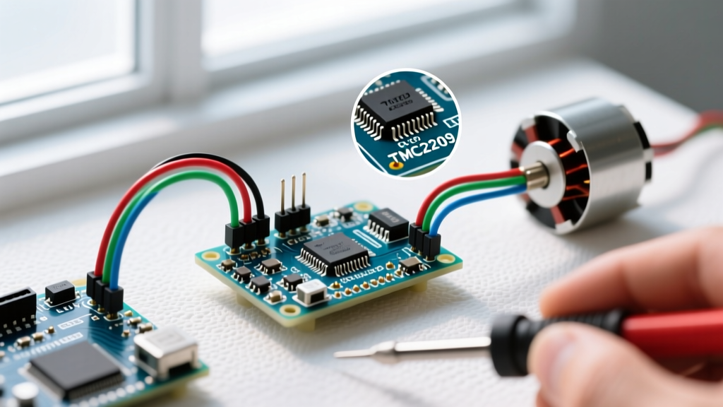

Beyond the A4988: Why the TMC2209 is the 2026 Standard
For years, the A4988 and DRV8825 were the default choices for hobbyists building a stepper motor controller Arduino setup. But as DIY CNC routers, camera sliders, and desktop robotic arms demand higher precision and lower acoustic noise, those legacy drivers fall short. Enter the Trinamic TMC2209 (now manufactured by Analog Devices). In 2026, it remains the undisputed champion of silent, high-torque microstepping.
However, the TMC2209 is not a simple 'plug-and-play' step/direction driver. To unlock its full potential—specifically StealthChop2, SpreadCycle, and StallGuard4—you must understand its internal registers. This datasheet explainer breaks down the critical silicon specifications, UART interfacing, and hardware failure modes you need to know before wiring this IC to your Arduino.
Core Silicon: What the Datasheet Actually Says
Before writing a single line of code, we must respect the electrical boundaries defined in the official Analog Devices TMC2209 datasheet. Pushing these limits is the number one cause of dead driver boards in community forums.
| Parameter | Datasheet Value | Practical 2026 Recommendation |
|---|---|---|
| VMOT (Motor Supply Voltage) | 4.75V to 29V (Max 36V transient) | Use 12V or 24V PSU. Avoid 36V to prevent transient spikes. |
| VCC_IO (Logic Supply) | 3V to 5.5V | Tie to Arduino 5V pin. Do NOT use 3.3V on standard 5V boards. |
| Continuous RMS Current | 2.0A per phase (with adequate cooling) | Limit to 1.5A RMS without active heatsink/fan cooling. |
| Microstep Resolution | Up to 256 microsteps | Use 16 or 32 for optimal torque-to-smoothness ratio. |
Expert Warning: The datasheet explicitly warns against disconnecting the motor windings while VMOT is powered. Doing so causes inductive kickback that will instantly puncture the internal H-bridge MOSFETs. Always power down the main supply before swapping NEMA 17 or NEMA 23 motors.
Pinout & UART Interfacing: The Arduino Connection
The TMC2209 operates in two distinct modes: Standalone (Step/Dir) and UART. While Standalone mode mimics older drivers using physical MS1/MS2 pins for microstepping, UART mode allows your Arduino to dynamically rewrite the driver's internal registers on the fly.
UART Wiring Matrix for Arduino Uno/Mega
To use the TMCStepper Arduino Library, you need a single-wire UART connection. The TMC2209 uses a half-duplex serial protocol.
- VMOT: Connect to 12V/24V PSU positive.
- GND: Connect to PSU ground AND Arduino ground (common ground is mandatory).
- VCC_IO: Connect to Arduino 5V.
- TX/RX (PDN_UART): Connect to an Arduino digital pin (e.g., Pin 10) via a 1kΩ resistor. The datasheet requires this resistor to prevent bus contention during half-duplex switching.
- STEP & DIR: Connect to Arduino digital pins (e.g., Pins 2 and 3).
- DIAG: Connect to an Arduino interrupt pin (e.g., Pin 2) if using StallGuard4 for sensorless homing.
Decoding the Chopper Modes: StealthChop2 vs. SpreadCycle
Section 5 of the datasheet details the motor control algorithms. Understanding when to switch between them is the hallmark of an advanced stepper motor controller Arduino build.
StealthChop2 (Silent Operation)
StealthChop2 uses a voltage-based PWM chopper. It is virtually silent at low to medium speeds, making it ideal for 3D printer extruders, camera sliders, and optical inspection rigs. However, the datasheet notes that voltage chopping inherently sacrifices high-speed torque. If your application requires rapid acceleration above 500 RPM, StealthChop2 may cause missed steps.
SpreadCycle (High-Torque Operation)
SpreadCycle is a current-based hysteresis chopper. It generates audible acoustic noise (a high-pitched whine) but delivers maximum torque and prevents mid-band resonance. Use SpreadCycle for CNC Z-axes, robotic joints, and high-inertia conveyors.
Pro Tip: The TMC2209 allows you to set a velocity threshold (TPWMTHRS register). You can configure the driver to use StealthChop2 at low speeds for silent idling, and automatically switch to SpreadCycle when the Arduino commands high-speed travel.
StallGuard4: Sensorless Homing Explained
Traditional limit switches require physical wiring and mounting brackets. The TMC2209's StallGuard4 feature measures the back-EMF (electromotive force) of the motor to detect mechanical load. When the motor hits a physical hard stop, the load spikes, and the driver pulls the DIAG pin HIGH.
To implement this in your Arduino code, you must configure the SGTHRS (StallGuard Threshold) register. According to the Arduino TMCStepper reference documentation, this value ranges from 0 to 255. A value of 0 represents the highest sensitivity (triggers easily), while 255 is the lowest. Most NEMA 17 setups require a threshold between 40 and 80, calibrated empirically via the serial monitor.
Calculating Current Limits: VREF vs. UART
If you are using the driver in Standalone mode, you must set the current limit using the onboard potentiometer. The datasheet provides the following formula for the RMS current:
I_RMS = (V_REF * 2) / (1.32 * R_SENSE)
Most generic TMC2209 breakout boards in 2026 use 0.11Ω sense resistors. Therefore, to achieve a safe 1.2A RMS for a standard NEMA 17 motor:
V_REF = (1.2 * 1.32 * 0.11) / 2 = 0.087V
driver.IRMS(1.2) command in the TMCStepper library, the Arduino writes the exact current limit directly to the digital-to-analog converter inside the IC, bypassing the analog potentiometer entirely.
Arduino Implementation: UART Initialization Code
Below is a robust initialization sequence using the TMCStepper library. This configures the driver for 16 microsteps, enables StealthChop2, and sets a safe 1.2A RMS current limit.
#include <TMCStepper.h>

#define EN_PIN    8
#define STEP_PIN  2
#define DIR_PIN   3
#define SW_PIN    10  // UART PDN_UART pin
#define R_SENSE   0.11f

TMC2209Stepper driver(&Serial1, R_SENSE, 0); // Use HardwareSerial1

void setup() {
  Serial1.begin(115200); // TMC2209 default UART baud rate

  pinMode(EN_PIN, OUTPUT);
  pinMode(STEP_PIN, OUTPUT);
  pinMode(DIR_PIN, OUTPUT);
  digitalWrite(EN_PIN, LOW); // Enable driver

  driver.begin();
  driver.toff(5);         // Enables driver in software
  driver.rms_current(1200); // Set 1.2A RMS current
  driver.microsteps(16);    // 1/16 microstepping
  driver.en_spreadCycle(false); // False = StealthChop2 enabled
  driver.pwm_autoscale(true);   // Required for StealthChop
}

void loop() {
  digitalWrite(DIR_PIN, HIGH);
  for (int i = 0; i < 3200; i++) { // 1 full rotation at 16 microsteps
    digitalWrite(STEP_PIN, HIGH);
    delayMicroseconds(160);
    digitalWrite(STEP_PIN, LOW);
    delayMicroseconds(160);
  }
}
Common Failure Modes & Datasheet Warnings
Even with perfect code, hardware oversights will destroy your TMC2209. Watch out for these three specific failure modes:
- Missing VMOT Decoupling: The datasheet strictly mandates a 100µF electrolytic capacitor placed as close to the VMOT and GND pins as possible. Without it, long motor wires act as antennas, reflecting voltage spikes back into the driver and triggering the internal thermal shutdown (or causing permanent silicon damage).
- Logic Level Mismatch: If you are using a 3.3V Arduino (like the Due or Zero), you must power the TMC2209 VCC_IO pin with 3.3V. Feeding 5V into VCC_IO while the MCU outputs 3.3V logic will cause the driver to misread UART commands, leading to erratic microstepping.
- Thermal Throttling: The IC features an overtemperature pre-warning flag at 120°C and a hard shutdown at 150°C. If your Arduino randomly loses steps after 10 minutes of operation, query the
DRV_STATUSregister via UART to check theot(overtemperature) andotpw(overtemperature pre-warning) bits. You may need to lower the RMS current or add a 5V cooling fan.
Frequently Asked Questions
Can I use the TMC2209 with a standard Arduino Stepper library?
Yes, but only in Standalone (Step/Dir) mode. You will lose access to UART features like dynamic current scaling, StallGuard4, and StealthChop configuration. For full functionality, the TMCStepper library is mandatory.
Why is my motor vibrating but not turning?
This usually indicates a wiring error in the motor coils (e.g., mixing up the A and B phase pairs) or the RMS current being set too low to overcome the motor's detent torque. Verify coil pairs with a multimeter (they should show 1-5 ohms of continuity) and increase the rms_current value in your code.
Is the TMC2209 compatible with 3.3V microcontrollers like the ESP32?
Absolutely. The ESP32 is an excellent choice for a stepper motor controller Arduino alternative. Just ensure you wire the ESP32's 3.3V output to the TMC2209's VCC_IO pin, and use a 1kΩ series resistor on the UART TX line to protect the ESP32's GPIO pins from 5V back-feed if the driver's VMOT is active before logic power.