
Mastering the I2C OLED Interface
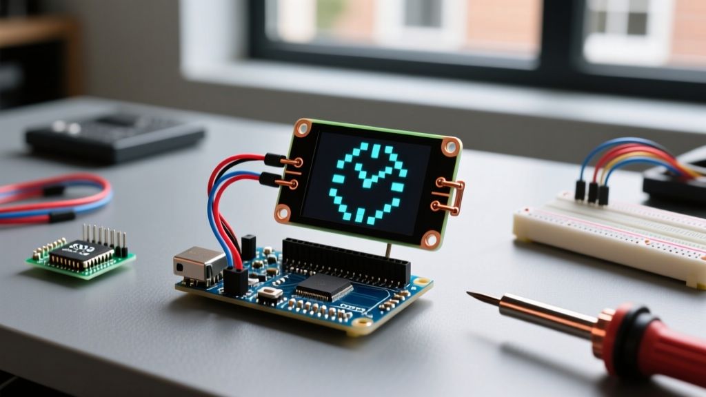
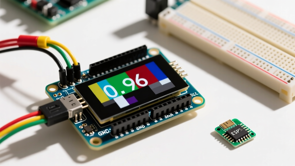
Integrating a monochrome OLED screen into your microcontroller projects is a rite of passage for electronics enthusiasts. The ubiquitous 0.96-inch 128x64 OLED module, typically driven by the SSD1306 controller, remains a staple in 2026 due to its high contrast, wide viewing angles, and low power consumption. However, the simplicity of the four-pin I2C interface often masks underlying electrical nuances. A proper understanding of the OLED Arduino display GND VCC SDA SCL configuration is critical to avoid flickering screens, I2C bus lockups, and permanent hardware damage.
While these modules are incredibly affordable—ranging from $2.50 for bulk clones to $6.00 for premium brands like Adafruit or SparkFun—they lack standardization in onboard voltage regulation. This guide bypasses generic tutorials and dives deep into the electrical realities, wiring topologies, and C++ code structures required to drive these displays reliably.
Pinout Breakdown: GND, VCC, SDA, and SCL
Before connecting jumper wires, you must understand what each pin expects electrically. The I2C (Inter-Integrated Circuit) protocol relies on a two-wire serial bus, but power delivery is equally important.
| Pin Label | Function | Arduino Uno/Nano Target | Electrical Characteristics & Notes |
|---|---|---|---|
| GND | Ground Reference | GND | Must share a common ground with the MCU. Crucial for I2C signal integrity. |
| VCC | Power Supply | 5V or 3.3V | Varies by module. Some have onboard LDOs (accept 5V), while raw panels require exactly 3.3V. |
| SCL | Serial Clock | A5 (Uno/Nano) | Requires a pull-up resistor. Drives the timing of the data bits. |
| SDA | Serial Data | A4 (Uno/Nano) | Bidirectional data line. Also requires a pull-up resistor to the logic high voltage. |
The Pull-Up Resistor Requirement
I2C is an open-drain protocol. The MCU and the OLED display can only pull the SDA and SCL lines LOW; they cannot drive them HIGH. To achieve a logic HIGH, external pull-up resistors are required. According to the SparkFun I2C Tutorial, standard I2C buses use 2.2kΩ to 4.7kΩ resistors. Most reputable OLED breakout boards include 4.7kΩ surface-mount pull-ups on the SDA and SCL lines. However, ultra-cheap clone modules often omit these to save fractions of a cent, leading to floating lines and random I2C address failures. If your bus scanner fails to find the display, check the PCB underside for missing R1/R2 resistors and add external 4.7kΩ pull-ups to the VCC rail.
Microcontroller-Specific Wiring Topologies
The physical pins for SDA and SCL change depending on the Arduino board architecture. Wiring the OLED Arduino display GND VCC SDA SCL correctly requires consulting the specific board's I2C hardware mapping.
- Arduino Uno / Nano (ATmega328P): SDA is tied to Analog Pin A4. SCL is tied to Analog Pin A5. Note that older Nano revisions sometimes route I2C to A4/A5 but lack the dedicated SDA/SCL headers near the AREF pin.
- Arduino Mega 2560: SDA is Digital Pin 20. SCL is Digital Pin 21. Wiring to A4/A5 on a Mega will result in a dead display, as those pins are not routed to the hardware TWI (Two-Wire Interface) peripheral.
- Arduino Nano 33 IoT / ESP32 Dev Kits: These 3.3V logic boards have dedicated SDA/SCL pins. Always use the 3.3V output for VCC on these boards to prevent logic level mismatch.
Critical Edge Case: The 3.3V vs 5V Logic Trap
The most common cause of premature OLED failure and erratic behavior in 2026 DIY projects is logic level mismatching. The SSD1306 controller operates internally at 3.3V. When you connect an OLED module to a 5V Arduino Uno, two scenarios occur based on the module's design:
- Modules with Onboard Charge Pump & LDO: These have a small voltage regulator. You wire VCC to 5V, and the onboard LDO drops it to 3.3V for the controller. The SDA/SCL lines are usually 5V tolerant via a simple MOSFET level shifter or resistor divider.
- Raw 'Bare-Bones' Modules: These lack regulation. If you wire VCC to 5V, you will instantly overvoltage the silicon, destroying the display. Furthermore, feeding 5V logic into the 3.3V SDA/SCL pins will cause latch-up and degradation over time.
Expert Tip: If you are using a 5V Arduino with a raw 3.3V OLED, you must use a bidirectional logic level converter (like the BSS138 MOSFET-based shifters from SparkFun) between the Arduino and the display's SDA/SCL pins. Do not rely on series resistors for level shifting on high-speed I2C buses, as they distort the signal rise times.
I2C Addressing and Bus Scanning
Before uploading rendering code, you must verify the I2C address. The SSD1306 typically uses 0x3C or 0x3D (7-bit addressing). Some Chinese datasheets list the address as 0x78 or 0x7A, which is the 8-bit equivalent including the read/write bit. The Arduino Wire library strictly uses 7-bit addressing.
Use this minimal I2C Scanner sketch to verify your OLED Arduino display GND VCC SDA SCL wiring before attempting to load heavy graphics libraries.
#include <Wire.h>

void setup() {
  Wire.begin();
  Serial.begin(115200);
  while (!Serial); // Wait for serial monitor
  Serial.println("Scanning I2C Bus...");
}

void loop() {
  byte error, address;
  int deviceCount = 0;

  for(address = 1; address < 127; address++ ) {
    Wire.beginTransmission(address);
    error = Wire.endTransmission();

    if (error == 0) {
      Serial.print("I2C device found at address 0x");
      if (address < 16) Serial.print("0");
      Serial.println(address, HEX);
      deviceCount++;
    }
  }
  if (deviceCount == 0) Serial.println("No I2C devices found. Check SDA/SCL wiring.");
  delay(5000);
}
Rendering Code: Adafruit SSD1306 vs. U8g2
Once your hardware is verified, you need a graphics library. The two dominant choices in the Arduino ecosystem are the Adafruit SSD1306 Library and the U8g2 library by Olikraus.
Option A: Adafruit SSD1306 (Best for Beginners)
The Adafruit library uses a framebuffer approach. For a 128x64 display, it allocates 1024 bytes of SRAM to store the screen state before pushing it over I2C. On an ATmega328P with only 2KB of SRAM, this consumes 50% of your available memory, leaving little room for sensor arrays or WiFi buffers.
#include <Wire.h>
#include <Adafruit_GFX.h>
#include <Adafruit_SSD1306.h>

#define SCREEN_WIDTH 128
#define SCREEN_HEIGHT 64
#define OLED_RESET     -1
#define SCREEN_ADDRESS 0x3C

Adafruit_SSD1306 display(SCREEN_WIDTH, SCREEN_HEIGHT, &Wire, OLED_RESET);

void setup() {
  Serial.begin(115200);
  if(!display.begin(SSD1306_SWITCHCAPVCC, SCREEN_ADDRESS)) {
    Serial.println(F("SSD1306 allocation failed"));
    for(;;); // Halt execution
  }
  display.clearDisplay();
  display.setTextSize(1);
  display.setTextColor(SSD1306_WHITE);
  display.setCursor(0,0);
  display.println("ElectricalFlux");
  display.display();
}

void loop() {}
Option B: U8g2 (Best for Memory-Constrained MCUs)
If you are pushing the limits of the Arduino Uno or integrating the OLED into a complex sensor node, switch to U8g2. It offers a 'page buffer' mode that requires only ~256 bytes of RAM. It also natively supports the SH1106 controller, which is frequently mislabeled as an SSD1306 on 1.3-inch OLED modules. Using the wrong driver for an SH1106 results in a 'ghosting' effect where the screen shifts horizontally by a few pixels.
Troubleshooting Bus Capacitance and Flickering
If your OLED display works on a breadboard but flickers or fails when installed in a project enclosure with longer wires, you have hit the I2C bus capacitance limit. The official NXP I2C specification limits bus capacitance to 400pF. Long, unshielded jumper wires act as capacitors, rounding off the sharp square-wave edges of the SCL clock signal. The Arduino I2C Documentation notes that signal degradation leads to missed ACK bits.
Solutions for Long Wire Runs:
- Twisted Pair Wiring: Twist the SDA and GND wires together, and the SCL and VCC wires together to reduce electromagnetic interference and loop area.
- Lower the Clock Speed: By default, the Arduino Wire library runs I2C at 100kHz (Standard Mode) or 400kHz (Fast Mode). You can drop the speed to 50kHz to allow more time for the RC circuit to charge. Add
Wire.setClock(50000);immediately afterWire.begin();. - Active Pull-Ups: Replace standard 4.7kΩ resistors with active I2C bus accelerators (like the LTC4311), which inject current into the line to overcome high capacitance.
Final Integration Checklist
Before finalizing your project enclosure, verify the following:
1. Common ground established between MCU and OLED.
2. VCC voltage matches the specific module's onboard regulation capabilities.
3. I2C address confirmed via scanner (0x3C or 0x3D).
4. Pull-up resistors present (either onboard or external).
5. Wire length kept under 30cm to maintain signal integrity without active acceleration.
By respecting the electrical realities of the OLED Arduino display GND VCC SDA SCL interface, you transition from simply copying tutorials to engineering robust, production-ready embedded displays.