
The GPIO Bottleneck in Multi-Sensor Projects
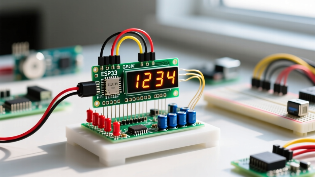
Building a comprehensive environmental monitor, robotics dashboard, or automated brewing controller often leads to a common microcontroller crisis: GPIO starvation. When your design requires a BME280 environmental sensor, an SPI-based SD card logger, a UART GPS module, and a motor controller, finding the spare pins to wire up a standard 7 segment display Arduino project becomes a mathematical puzzle.
A standard 4-digit 7-segment display requires 12 GPIO pins if multiplexed directly from the microcontroller. In a multi-peripheral setup, sacrificing 12 pins is simply not an option. Furthermore, direct multiplexing demands constant, high-frequency timer interrupts to prevent flickering, which can introduce latency or jitter when polling time-sensitive peripherals like rotary encoders or PIR motion sensors.
To solve this, engineers must offload the display driving logic to dedicated peripheral ICs. Below, we break down the three most effective architectures for integrating a 7-segment display into a crowded microcontroller ecosystem, analyzing their electrical footprints, bus protocols, and edge cases.
Pin Consumption & Protocol Matrix
Before selecting a driver, it is critical to understand how different modules interact with your microcontroller's communication buses. The following matrix compares the most common 7-segment integration methods available in 2026.
| Driver Method | Protocol | GPIO Pins Used | Bus Contention Risk | Typical Cost (USD) |
|---|---|---|---|---|
| Direct Multiplexing | Parallel GPIO | 12 | High (CPU blocking) | $1.50 (Raw display) |
| TM1637 Module | Custom 2-Wire | 2 | High (Blocking delays) | $1.80 |
| HT16K33 Backpack | True I2C | 2 | Low (Hardware buffered) | $9.50 (Adafruit) |
| 74HC595 Shift Register | SPI / Bit-Bang | 3 | Medium (SPI bus sharing) | $0.45 |
| MAX7219 Driver | SPI | 3 | Low (Hardware SPI) | $2.50 |
Architecture 1: True I2C Integration via HT16K33
If your multi-peripheral setup already relies heavily on the I2C bus (e.g., sharing lines with an OLED display and a BME280 sensor), the HT16K33 I2C backpack is the optimal choice. Unlike raw displays, the HT16K33 contains a dedicated RAM buffer and an internal oscillator that handles multiplexing autonomously. You only need to send an I2C payload when the displayed value changes, freeing the microcontroller's CPU to handle sensor polling.
I2C Address Mapping and Bus Capacitance
The base I2C address for the HT16K33 is 0x70. By soldering the A0, A1, and A2 jumpers on the PCB, you can offset this address up to 0x77. This is crucial in multi-peripheral setups to avoid address collisions with other sensors.
Expert Warning: I2C Bus Capacitance
According to the NXP I2C-bus specification (UM10204), the maximum allowable bus capacitance is 400pF. When you daisy-chain an OLED, a BME280, and an HT16K33 backpack on the same SDA/SCL lines, the parasitic capacitance of the traces and breakout boards can easily exceed this limit, resulting in corrupted data or ACK failures. If your trace length exceeds 30cm, you must reduce the I2C pull-up resistors from the standard 4.7kΩ down to 2.2kΩ or even 1kΩ to sharpen the signal rise times.
Architecture 2: Offloading to SPI via 74HC595 Shift Registers
If your I2C bus is already congested, or if you are running long wires in an electrically noisy environment (such as near stepper motor drivers), moving the display to the SPI bus is a superior strategy. The Texas Instruments 74HC595 shift register allows you to control 8 output pins using only 3 microcontroller GPIOs: Serial Data (SER), Shift Register Clock (SRCLK), and Storage Register Clock (RCLK).
Implementing Hardware SPI for Non-Blocking Updates
Many basic tutorials use shiftOut() with software bit-banging. In a multi-peripheral setup, software bit-banging disables interrupts and blocks the CPU, which can cause you to miss incoming UART bytes from a GPS module or drop I2C transactions. Instead, utilize the Arduino's hardware SPI pins (MOSI and SCK on the ATmega328P) combined with a dedicated Latch pin. The Arduino SPI and Wire libraries handle the clock cycles in the background via hardware registers, ensuring your sensor polling loops remain uninterrupted.
The 'Fake I2C' Trap: Why TM1637 Fails in Complex Setups
The TM1637 4-digit display module is ubiquitous in starter kits due to its low $1.80 price point. It uses a custom 2-wire protocol that resembles I2C but lacks proper start/stop conditions and ACKnowledge bits. More critically, the standard Arduino libraries for the TM1637 rely heavily on delayMicroseconds() to bit-bang the protocol.
In a simple clock project, this is fine. In a multi-peripheral setup where you are simultaneously reading a DHT22 sensor and debouncing a mechanical button, these blocking delays will introduce severe timing jitter. If your project requires real-time responsiveness across multiple peripherals, avoid the TM1637 and opt for the hardware-buffered HT16K33 or MAX7219.
Power Delivery and Electrical Limits
A frequently overlooked failure mode in multi-peripheral wiring is exceeding the microcontroller's current sourcing limits. A standard 4-digit 7-segment display with all segments illuminated (including decimal points) draws approximately 8mA per segment. With 32 segments active, the total current draw approaches 256mA.
- ATmega328P Absolute Maximum: 40mA per I/O pin, and a total package limit of 200mA for VCC/GND combined.
- ESP32 Limits: Even more restrictive, with a recommended maximum of 12mA per GPIO and strict total LDO limits on development boards.
The Solution: Never power a multi-digit display directly from the microcontroller's 5V/3.3V regulator pin. Wire the VCC of the display driver directly to the main power supply rail (e.g., a dedicated 5V 2A buck converter). Use the microcontroller only for logic-level signaling. If using raw displays with shift registers, ensure the shift register IC is rated for the current, or use a ULN2803 Darlington transistor array to handle the heavy sinking current.
Step-by-Step Integration Matrix: 3-Peripheral Setup
Below is a proven wiring topology for integrating a 7-segment display alongside an environmental sensor and an OLED screen on an Arduino Uno (ATmega328P) without bus collisions.
- Power Rail: Connect an external 5V 1.5A switching power supply to the breadboard's main power rails. Connect the GND of this supply to the Arduino GND to establish a common ground reference.
- I2C Bus (Sensors & Display):
- BME280 (Address 0x76): SDA to A4, SCL to A5.
- SSD1306 OLED (Address 0x3C): SDA to A4, SCL to A5.
- HT16K33 7-Segment (Address 0x70): SDA to A4, SCL to A5.
- Pull-Up Resistors: Install a single pair of 2.2kΩ resistors between the 5V rail and the SDA/SCL lines. Do not use the breakout boards' onboard pull-ups if they exceed 10kΩ, as the parallel resistance will become unpredictable.
- Logic Level Shifting (If using ESP32): If you migrate this setup to a 3.3V ESP32, you must place a bidirectional logic level shifter (like the BSS138 MOSFET circuit) on the SDA/SCL lines before they reach the 5V HT16K33 backpack to prevent back-feeding voltage into the ESP32's GPIOs.
Edge Cases and Troubleshooting
Display Flickering Under Motor Load
If your 7-segment display flickers when a relay clicks or a DC motor spins, the issue is rarely software. It is almost always a lack of local decoupling capacitance. Solder a 100nF (0.1µF) ceramic capacitor directly across the VCC and GND pins of the shift register or I2C backpack. This provides a local energy reservoir to handle the instantaneous current spikes when multiple LED segments switch on simultaneously.
Ghosting Segments on Shift Registers
When using the 74HC595, you may notice faint 'ghost' segments lighting up during data transmission. This occurs because the data is being shifted into the internal register while the output pins are still active. To fix this, wire the OE (Output Enable) pin of the 74HC595 to a microcontroller GPIO. Pull OE HIGH to disable outputs before shifting new data, then pull OE LOW after the RCLK latch pin has been pulsed. This guarantees glitch-free visual updates.
Frequently Asked Questions
Can I use a 7-segment display on the same SPI bus as an SD card module?
Yes, provided they use separate Chip Select (CS) pins. The SD card will use its dedicated CS pin, while a MAX7219 7-segment driver will use a different GPIO as its LOAD/CS pin. Ensure the SD card library releases the SPI bus (via SD.end() or proper CS management) before writing to the display to prevent data corruption on the MISO/MOSI lines.
Why does my I2C scanner fail to find the 7-segment backpack when the OLED is connected?
This is usually caused by an I2C address collision or a voltage drop on the SDA line. Verify that the OLED (typically 0x3C or 0x3D) and the HT16K33 (0x70-0x77) do not share addresses. Next, measure the voltage on the SDA and SCL lines with a multimeter; if it reads below 4.5V on a 5V system, your pull-up resistors are too weak for the combined bus capacitance. Swap to 2.2kΩ resistors.