
The Hidden Limits of LiquidCrystal.h
For most makers, lcd arduino coding begins and ends with the standard LiquidCrystal.h library. You initialize the pins, call lcd.print(), and move on. But when you need to optimize memory, eliminate blocking delays in tight PID control loops, or debug ghosting characters on an I2C backpack, the abstraction layer becomes a liability. To truly master alphanumeric displays, you must read the Hitachi HD44780U Datasheet.
This datasheet explainer bridges the gap between silicon-level hardware specifications and high-level C++ implementation, revealing the exact timing, memory mapping, and initialization handshakes that separate novice scripts from production-grade firmware.
Memory Map Matrix: DDRAM vs. CGRAM vs. CGROM
The HD44780U controller manages three distinct memory blocks. Understanding how they map to physical pixels is the foundation of advanced display manipulation.
| Memory Type | Capacity | Function | Hex Address Range |
|---|---|---|---|
| DDRAM | 80 Bytes | Stores character codes currently displayed on the screen. | 0x00 - 0x4F (Line 1: 0x00-0x0F, Line 2: 0x40-0x4F) |
| CGRAM | 64 Bytes | Stores user-defined custom characters (up to eight 5x8 glyphs). | 0x00 - 0x3F |
| CGROM | 9920 Bits | Read-only memory containing the standard ASCII/ROM character font. | N/A (Accessed via DDRAM character codes) |
The Line 2 Offset Trap
A common failure mode in custom scrolling code is assuming Line 2 starts at memory address 0x10. The datasheet explicitly maps the first line to 0x00 - 0x27 (for a 40-character internal buffer) and the second line to 0x40 - 0x67. If you write a raw memory loop incrementing by 1 from 0x0F, your text will vanish into the void of the internal buffer before reappearing on Line 2 at 0x40. Proper lcd arduino coding requires conditional address jumping or utilizing the auto-increment shift features defined in the Entry Mode Set instruction.
Register Selection: Decoding RS, R/W, and E
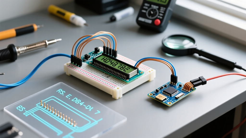
Communication with the LCD is governed by three control pins. While many tutorials hardwire the R/W (Read/Write) pin to GND to save a microcontroller GPIO, doing so blinds your code to the display's actual state.
- RS (Register Select): LOW = Instruction Register (IR) for commands like clearing the screen. HIGH = Data Register (DR) for sending ASCII characters.
- R/W (Read/Write): LOW = Write to LCD. HIGH = Read from LCD (crucial for polling the Busy Flag).
- E (Enable): A falling-edge triggered latch. Data is only captured by the HD44780 on the high-to-low transition of this pin.
Expert Insight: By tying R/W to GND, you force your Arduino to use blind delay() functions after every command. If you wire R/W to a GPIO pin, you can read the D7 data line. When D7 is HIGH, the LCD is busy processing. Polling the Busy Flag allows your microcontroller to execute other tasks and push the next byte the exact microsecond the LCD is ready.
Optimizing Execution Times in LCD Arduino Coding
The standard Arduino LiquidCrystal Reference library uses a conservative 2-millisecond delay for lcd.clear() and lcd.home(). The datasheet tells a different story.
| Instruction | Datasheet Max Execution Time | Standard Library Delay | Optimization Strategy |
|---|---|---|---|
| Clear Display | 1.52 ms | 2.0 ms | Overwrite with spaces instead of clearing to avoid the 1.52ms penalty. |
| Return Home | 1.52 ms | 2.0 ms | Use Set DDRAM Address (0x02) to move cursor instantly (37 μs). |
| All Other Instructions | 37 μs | 40 μs (approx) | Use delayMicroseconds(40) instead of blocking millisecond delays. |
If you are logging high-frequency sensor data (e.g., a 1kHz IMU sampling rate), a 2ms blocking delay will cause you to drop samples. Overwriting existing DDRAM locations with new characters takes only 37 μs per byte, keeping your control loop intact.
The 4-Bit Initialization Handshake
The HD44780U powers up in 8-bit mode by default. To use 4-bit mode (saving 4 GPIO pins), you must perform a highly specific hardware handshake outlined on page 46 of the datasheet. If your code skips this, the LCD will occasionally boot into a garbled state, especially in cold environments where the internal oscillator starts slower.
- Wait at least 40ms after VDD reaches 4.5V.
- Send
0x03(8-bit mode command) via the upper nibble. Wait 4.1ms. - Send
0x03again. Wait 100μs. - Send
0x03a third time. Wait 100μs. - Send
0x02to lock the controller into 4-bit mode.
The I2C Backpack Latency Problem
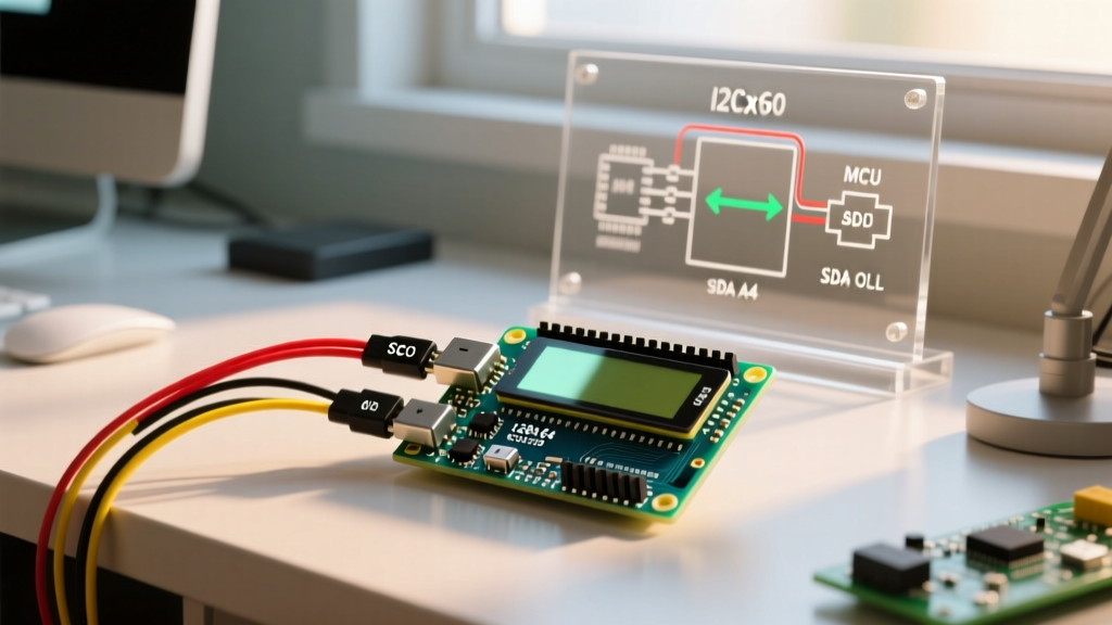
Modern lcd arduino coding heavily relies on PCF8574 I2C backpacks to reduce wiring to just SDA and SCL. However, as noted in Adafruit's I2C LCD Guide, the I2C bus speed (typically 100kHz or 400kHz) introduces latency. The PCF8574 expander requires I2C transactions to toggle the Enable (E) pin. This means a single 4-bit nibble transfer takes roughly 50μs over I2C, compared to 2μs over direct GPIO. When writing custom I2C drivers, you must account for this bus latency, or the LCD's Enable pin will pulse too fast for the HD44780 to latch the data.
Engineering Custom Characters via CGRAM
The CGRAM allows you to define up to eight 5x8 pixel custom glyphs. To write to CGRAM, you must set the CGRAM address pointer before sending data.
Step-by-Step CGRAM Addressing:
- Command 0x40: Sets the CGRAM address to 0x00 (Custom Character 0).
- Command 0x48: Sets the CGRAM address to 0x08 (Custom Character 1).
- Command 0x50: Sets the CGRAM address to 0x10 (Custom Character 2).
Each character requires 8 bytes of data. The lower 5 bits of each byte represent the pixels (1 = ON, 0 = OFF), while the upper 3 bits must be kept LOW. Once written to CGRAM, you print the custom character to the screen by writing its index (0-7) to the DDRAM via the Data Register.
Hardware Edge Cases: V0, VDD, and Signal Integrity
Software cannot fix hardware bias issues. The V0 pin (Pin 3) controls the liquid crystal contrast. The datasheet specifies that V0 must be roughly 4.0V to 4.5V lower than VDD (Pin 2) for optimal contrast at 25°C.
- The Potentiometer Method: A standard 10kΩ trimpot between VDD and GND, with the wiper to V0, works but wastes current and is susceptible to vibration.
- The PWM Method (Advanced): You can drive V0 using an Arduino PWM pin filtered through a 10kΩ resistor and a 10μF capacitor to create a stable DC voltage. This allows dynamic contrast adjustment in code, which is highly useful if your device operates in extreme temperature ranges where LCD fluid viscosity changes.
- Signal Integrity on E: If using long jumper wires (>15cm) between the Arduino and the LCD, the Enable (E) pin is highly susceptible to capacitive coupling and noise. A 10kΩ pull-down resistor on the E pin ensures it stays LOW and prevents ghost-triggering from EMI generated by nearby stepper motors or relay modules.
By internalizing the HD44780U datasheet, your lcd arduino coding transitions from simple text printing to precise, cycle-accurate hardware control. Whether you are shaving microseconds off a data-logging routine or engineering robust I2C initialization sequences, the silicon-level truth is always found in the timing diagrams.