
The Anatomy of an OLED Display Failure
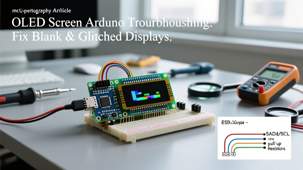
Integrating an OLED screen Arduino setup is a rite of passage for embedded developers. The ubiquitous 0.96-inch 128x64 I2C OLED modules—typically priced between $3 and $6 in 2026—are incredibly sharp, power-efficient, and easy to wire. However, they are also notorious for causing headaches. You upload your sketch, the Arduino compiles without errors, but the display remains stubbornly black, flickers randomly, or renders scrambled, offset pixels.
Blank displays are rarely caused by a completely dead module right out of the box. Instead, 90% of failures stem from I2C bus capacitance issues, controller mismatches, or SRAM exhaustion on 8-bit AVR microcontrollers. This systematic troubleshooting guide will walk you through the physical, protocol, and software layers to get your display running flawlessly.
Quick Diagnostic Matrix
Before diving into the wiring, identify your exact symptom using this diagnostic matrix to pinpoint the failure layer.
| Symptom | Probable Root Cause | Quick Fix / Action |
|---|---|---|
| Completely Blank / No Backlight | Power delivery failure or dead I2C address | Verify VCC/GND continuity; run I2C Scanner sketch. |
| Image Shifted by 2 Pixels or Scrambled | SH1106 controller masquerading as SSD1306 | Switch from Adafruit_SSD1306 to Adafruit_SH110X. |
| Flickering or Random Resets | Voltage sag on I2C lines or missing pull-ups | Add 4.7kΩ pull-up resistors and a 100nF decoupling capacitor. |
| Freezes After 1–5 Minutes | SRAM exhaustion / Memory leak on ATmega328P | Use the F() macro for strings; switch to U8g2 page buffer. |
| Works on Uno, Fails on ESP32 | Logic level mismatch (5V vs 3.3V) | Implement a BSS138 logic level shifter on SDA/SCL lines. |
Phase 1: Physical Layer & Wiring Verification
The most common point of failure in any OLED screen Arduino project is the physical connection. While I2C only requires four wires (GND, VCC, SDA, SCL), the bus is highly sensitive to noise and capacitance.
The Silkscreen Bait-and-Switch
Many budget I2C OLED modules manufactured overseas feature incorrect silkscreen labels. It is remarkably common to find boards where the SDA and SCL pins are swapped compared to the printed text. If your display is blank, physically swap the SDA and SCL wires at the microcontroller end as your very first troubleshooting step.
I2C Bus Capacitance and Pull-Up Resistors
The I2C protocol relies on open-drain communication. This means the microcontroller pulls the line LOW, but relies on external pull-up resistors to bring the line HIGH. According to the official Arduino Wire library documentation, the internal pull-ups on an ATmega328P (roughly 20kΩ to 50kΩ) are often too weak to overcome the capacitance of the OLED module's PCB traces and your jumper wires.
- The Fix: Solder or breadboard two 4.7kΩ resistors between the SDA/SCL lines and the VCC (3.3V or 5V) line.
- Wire Length Limit: Keep your I2C jumper wires under 30cm (12 inches). Beyond this length, parasitic capacitance degrades the square wave into a sawtooth, causing the OLED controller to miss clock pulses and lock up.
Phase 2: Protocol Layer & Address Detection
If the wiring is correct and pull-ups are installed, the next step is to verify that the Arduino can actually see the display on the I2C bus. Most SSD1306 modules ship with an I2C address of 0x3C or 0x3D. However, a broken trace or a blown internal voltage regulator can cause the module to drop off the bus entirely.
Running the I2C Scanner
Upload the standard I2CScanner example sketch (found in the Arduino IDE under File > Examples > Wire). Open the Serial Monitor at 9600 baud.
Expert Insight: If the scanner returns 'No I2C devices found', measure the voltage between the OLED's VCC and GND pins with a multimeter. You should read a stable 5.0V (or 3.3V). If you read 0V, your breadboard power rail is disconnected. If you read 2.1V, the module's internal LDO regulator is shorted, and the unit is defective.
As detailed in Adafruit's comprehensive OLED guide, some modules include a physical resistor jumper on the back labeled 'I2C ADDR'. If this resistor is moved, the address shifts. Ensure your initialization code matches the address found by the scanner.
Phase 3: The Controller Mismatch (SSD1306 vs. SH1106)
You ordered an SSD1306 display, the I2C scanner sees it at 0x3C, your code compiles, but the image is shifted two pixels to the right, or the top/bottom edges are wrapped around. Welcome to the most frustrating edge case in DIY electronics.
Why This Happens
Due to supply chain fluctuations, many manufacturers swap the internal driver IC. The SH1106 controller is pin-compatible and functionally identical to the SSD1306, with one major difference: the SH1106 has a display RAM of 132x64, while the SSD1306 is exactly 128x64. When you send 128 columns of data to an SH1106 using an SSD1306 library, the controller offsets the image into its 132-column memory space, resulting in a corrupted or shifted display.
The Software Fix
- Open the Arduino Library Manager.
- Install the
Adafruit SH110Xlibrary. - Change your initialization object from
Adafruit_SSD1306toAdafruit_SH1106G. - Alternatively, use the highly optimized U8g2 library wiki which auto-handles many of these controller quirks via specific constructor selections (e.g.,
U8G2_SH1106_128X64_NONAME_F_HW_I2C).
Phase 4: Software Layer & SRAM Starvation
If your OLED screen Arduino setup works perfectly for three minutes and then completely freezes, requiring a hard reset, you are likely experiencing SRAM exhaustion. This is highly specific to 8-bit AVR boards like the Arduino Uno R3 or Nano (ATmega328P).
The Math Behind the Crash
The ATmega328P has exactly 2,048 bytes of SRAM. A standard 128x64 OLED requires a framebuffer to render graphics. The math is simple: (128 pixels × 64 pixels) / 8 bits per byte = 1,024 bytes. The moment you initialize the display, 50% of your microcontroller's total memory is consumed just to hold the screen image.
If your code uses standard String objects, HTTP client buffers, or complex arrays, you will silently overwrite the stack, causing a hard lockup.
Optimization Strategies
- Use the F() Macro: Never pass raw text to the display. Change
display.println("Temperature:");todisplay.println(F("Temperature:"));. This forces the compiler to read the string directly from Flash memory (32KB) instead of copying it into precious SRAM. - Switch to Page Buffering: If using the U8g2 library, avoid the
_F_(full buffer) constructors. Instead, use the_1_(page buffer) constructors, which render the screen in 8-pixel high horizontal stripes, reducing the OLED memory footprint from 1024 bytes to just 128 bytes.
Phase 5: Logic Level Disasters (ESP32 & ARM)
When upgrading from a 5V Arduino Uno to a 3.3V microcontroller like the ESP32-S3 or Raspberry Pi Pico, developers often encounter dead I2C buses. While the OLED module itself might accept 5V at the VCC pin, the I2C data lines (SDA/SCL) on modern 3.3V microcontrollers are not 5V tolerant.
Connecting a 5V-pulled-up I2C bus directly to an ESP32 GPIO pin can permanently fry the microcontroller's internal ESD protection diodes. If your ESP32 is no longer detected by your PC via USB after wiring up an OLED, the GPIO bank is likely destroyed.
The Proper Interfacing Solution
To safely interface a 5V OLED module with a 3.3V microcontroller, you must use a bidirectional logic level shifter. The BSS138 N-channel MOSFET circuit is the industry standard for I2C level translation. It safely shifts the 5V pull-up signals down to 3.3V without introducing the propagation delay associated with standard IC shifters like the 74HC595. A pre-built BSS138 breakout board costs roughly $1.50 and will save your $8 ESP32 from an early grave.
Summary Checklist for a Flawless Boot
Before assuming your OLED module is defective, run through this final verification checklist:
- Verify VCC is receiving a stable voltage (measure with a multimeter, don't trust the USB port).
- Confirm SDA/SCL are not swapped (check both code and physical silkscreen).
- Add 4.7kΩ pull-up resistors if using wires longer than 15cm.
- Run the I2C Scanner to confirm the 0x3C or 0x3D address.
- Verify you are using the correct library for your specific controller IC (SSD1306 vs SH1106).
- Implement the
F()macro to protect your AVR's SRAM.
By approaching your OLED screen Arduino integration systematically—moving from the physical wiring up to the software memory management—you will eliminate the guesswork and achieve a rock-solid, flicker-free display every time.