
The Legacy and Reality of the L298N in Modern Robotics
Despite the proliferation of modern MOSFET-based motor controllers, the L298N Arduino motor driver remains a staple in DIY robotics, educational kits, and automated prototypes. Its ruggedness, massive heatsink footprint, and ubiquitous availability (often priced between $2.00 and $4.00 for clone modules) make it the default choice for driving 12V DC gear motors and stepper motors. However, treating the L298N like a modern plug-and-play peripheral is a common pitfall. To extract reliable performance and avoid catastrophic thermal shutdowns, you must understand its underlying Bipolar Junction Transistor (BJT) architecture and pair it with the correct software libraries.
In this guide, we dissect the hardware realities of the L298N dual H-bridge, evaluate the best library abstractions for the Arduino ecosystem, and provide a definitive troubleshooting matrix for edge cases that plague intermediate builders.
Hardware Anatomy: BJT Voltage Drops and Thermal Limits
Unlike modern drivers such as the Texas Instruments DRV8833 which utilize MOSFETs with a negligible voltage drop (~0.4V), the L298N relies on Darlington BJT pairs. According to the STMicroelectronics L298N Datasheet, this architecture introduces a saturation voltage drop (Vce_sat) of roughly 2.0V to 3.0V across the H-bridge.
What this means for your build: If you supply 12V to the module's VCC terminal, your motor will only receive 9V to 10V under load. Furthermore, that missing 2V to 3V is dissipated directly as heat. At a continuous current draw of 1.5A per channel, the IC is burning off roughly 4.5W of thermal energy. Without active airflow or a properly seated thermal pad to the module's aluminum heatsink, the junction temperature will rapidly approach the 150°C internal thermal shutdown threshold.
L298N Module Pinout and Operating Thresholds
| Pin / Terminal | Function | Voltage / Logic Level | Critical Notes |
|---|---|---|---|
| 12V (VCC) | Motor Power Input | 5V to 35V (Max) | Do not exceed 12V if using the onboard 5V regulator. |
| GND | Common Ground | 0V | Must be shared with Arduino GND for logic reference. |
| 5V (Output) | Onboard Regulator Out | 5V (Max 500mA) | Can power the Arduino via VIN/5V pin if jumper is set. |
| ENA / ENB | PWM Speed Control | 5V Logic / PWM | Remove factory jumpers to enable PWM speed control. |
| IN1 - IN4 | Direction Logic | 5V Logic (HIGH/LOW) | Requires ~5mA per pin; easily driven by ATmega328P. |
The 5V Onboard Regulator Trap
Most generic L298N modules include a 7805 linear voltage regulator and a jumper cap located near the 12V terminal. This setup is designed to drop the motor supply voltage down to 5V to power the logic circuitry—and potentially your Arduino.
Pro-Tip: If your motor supply voltage exceeds 12V, you must remove the 5V jumper cap and power the module's logic via a separate 5V source or your Arduino's 5V pin. Supplying 24V to VCC with the jumper installed forces the 7805 to dissipate nearly 1W of heat (19V drop × 50mA), which will quickly destroy the uncooled SMD regulator on clone boards.
Library Showdown: Bare Metal vs. Abstraction
When integrating the L298N with an Arduino, developers generally choose between raw pin manipulation or dedicated object-oriented libraries. While the Arduino Official Motor Documentation provides excellent bare-metal examples, abstraction libraries save significant development time when managing acceleration ramps and multi-motor state machines.
1. Raw digitalWrite() and analogWrite()
For simple single-motor tests, raw pin control is optimal. You set IN1 HIGH and IN2 LOW for forward motion, and apply a PWM signal to ENA. This approach has zero overhead but becomes messy when managing four motors or implementing braking logic.
2. The AFMotor Library (Legacy)
Originally written for the Adafruit Motor Shield V1 (which used the L298), the AFMotor library is still widely copied in tutorials. However, it is heavily tied to the specific pin mappings of the shield and uses deprecated Timer configurations. It is not recommended for bare L298N modules in 2026.
3. The L298X / Generic OOP Libraries
Modern repositories like the L298X Motor Driver library (available via the Arduino Library Manager) provide a clean, hardware-agnostic OOP wrapper. You instantiate the motor by passing the EN, IN1, and IN2 pins, allowing for clean methods like motor.forward(speed) and motor.brake().
Step-by-Step: Implementing the L298X Library
Below is the definitive setup for driving a single DC gear motor using a modern OOP approach. Ensure you have installed a generic L298X library via the Arduino IDE Library Manager.
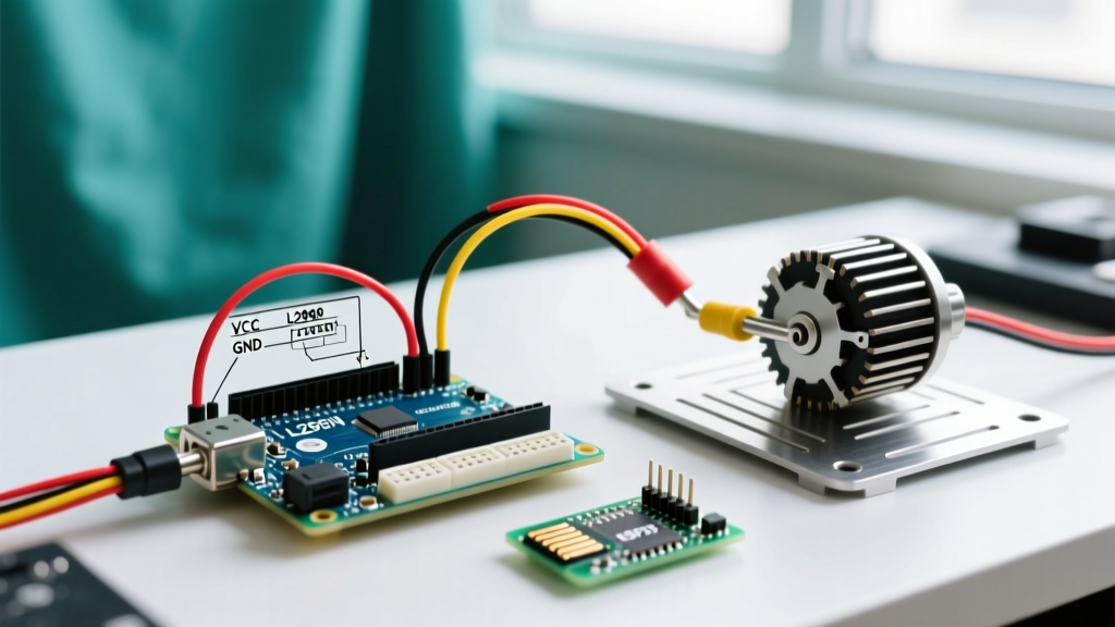
- Hardware Wiring: Connect Arduino Pin 9 to ENA, Pin 8 to IN1, and Pin 7 to IN2. Connect Arduino GND to the L298N GND terminal.
- Jumper Removal: Pull the jumper cap off the ENA pins on the L298N module to allow PWM control.
- Code Implementation:
#include <L298X.h>

// Initialize motor: ENA pin, IN1 pin, IN2 pin
L298X driveMotor(9, 8, 7);

void setup() {
  // Set initial speed (0-255)
  driveMotor.setSpeed(180);
}

void loop() {
  driveMotor.forward();
  delay(2000);

  // Active braking (shorts the motor terminals via the H-Bridge)
  driveMotor.brake();
  delay(1000);

  driveMotor.backward();
  delay(2000);

  driveMotor.stop(); // Coasts to a halt
  delay(1000);
}
Edge Cases: Flyback Diodes and PWM Whine
Even with perfect code, hardware physics can derail an L298N project. Here are the two most common advanced failure modes:
1. Flyback Diode Limitations at High PWM Frequencies
The L298N module includes eight 1N4007 rectifier diodes arranged to protect the BJT transistors from inductive voltage spikes when the motor coils are de-energized. While 1N4007 diodes are fine for low-frequency switching, they have a relatively slow reverse recovery time (~30µs). If you modify Arduino timers to output ultrasonic PWM frequencies (above 20kHz) to eliminate audible motor whine, the 1N4007 diodes cannot switch fast enough. This results in massive voltage spikes that can punch through the L298N's internal protection and fry the IC. Solution: Stick to the default Arduino PWM frequency (~490Hz or ~980Hz), or physically replace the board's diodes with fast-recovery UF4007 or Schottky diodes if high-frequency PWM is mandatory.
2. Audible PWM Whine and Micro-Vibrations
At low PWM duty cycles (below 60/255), the L298N's slow BJT switching combined with the motor's inductance can cause a high-pitched whine. This is not a defect; it is the physical vibration of the motor windings at the ~490Hz PWM frequency. To mitigate this without changing timer registers, implement a 'minimum start voltage' in your code. Instead of ramping from 0 to 255, start your PWM at 80 (enough to overcome static friction and inductance), then scale your control logic accordingly.
Frequently Asked Questions
Can I power a 5V logic Arduino directly from the L298N's 5V terminal?
Yes, but only if your motor supply (VCC) is between 7V and 12V, and the 5V jumper cap is installed. The onboard 7805 regulator can safely supply the ~50mA required by an ATmega328P microcontroller. However, if you are using a power-hungry board like an Arduino Mega with a TFT shield, the 7805 will overheat. In that case, power the Arduino independently.
Why is my L298N getting too hot to touch even with small motors?
The L298N is inherently inefficient due to its BJT design. A surface temperature of 60°C to 80°C during continuous operation is normal and within the silicon's safe operating area (junction temps up to 150°C). If the thermal shutdown is triggering (motor randomly stops and starts), you must either reduce the continuous current draw below 1.2A, add a forced-air fan, or upgrade to a modern MOSFET driver like the TB6612FNG.