
Beyond the Hookup Guide: Reading Capacitive Sensor Datasheets
Integrating a capacitive sensor Arduino project often starts with a simple hookup guide, but real-world reliability demands a deeper dive into the silicon. Capacitive touch sensing is notoriously sensitive to parasitic capacitance, environmental noise, and dielectric material properties. In 2026, while machine learning-based noise filtering is emerging in high-end mobile SoCs, hobbyist and prosumer microcontrollers still rely on the raw electrical characteristics defined in component datasheets.
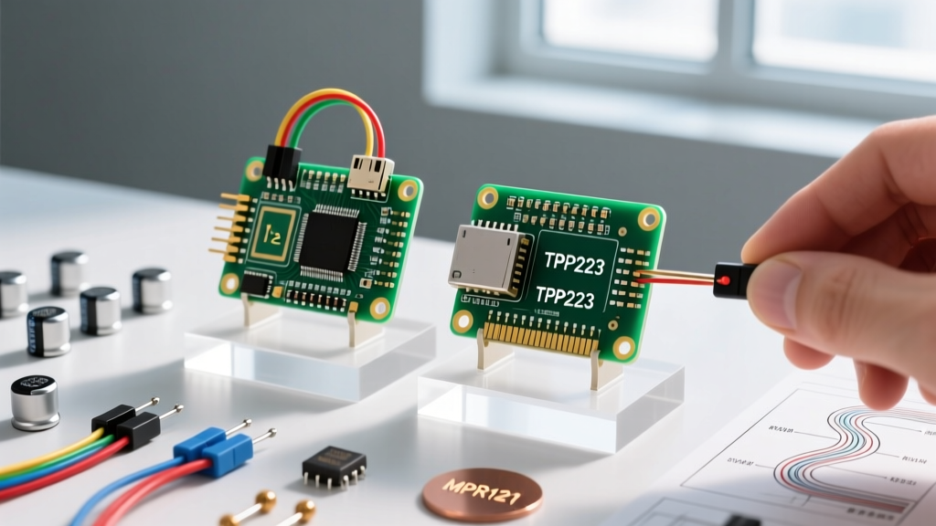
This guide decodes the datasheets of two ubiquitous capacitive touch ICs: the single-channel TTP223 and the 12-channel I2C powerhouse NXP MPR121. By understanding the register maps, timing diagrams, and electrical limits, you can transition from simply copying code to engineering robust touch interfaces.
The TTP223: Single-Channel Simplicity and Hardware Configuration
The TTP223 is the quintessential single-channel capacitive touch switch. It requires no I2C or SPI bus; it simply outputs a digital HIGH or LOW based on the state of its internal oscillator. However, the datasheet reveals critical hardware configuration options that most basic tutorials ignore.
Decoding the A/B Configuration Pads
On the back of a standard TTP223 breakout board, you will find two sets of solder pads labeled A and B. The datasheet defines these as the output mode and active state selectors:
- Pad A (Output Mode): Left open for momentary touch (output follows touch state). Bridged with solder for toggle mode (each touch toggles the output).
- Pad B (Active State): Left open for Active-High (outputs 3.3V/5V on touch). Bridged for Active-Low (outputs GND on touch).
Power Consumption and Sleep Timing
According to the TTP223 datasheet, the IC features an automatic sleep mode. After 10 seconds of no touch activity, the internal refresh cycle slows down, dropping current consumption from ~3mA to roughly 2.5µA. If your Arduino project is battery-powered, you must account for the wake-up latency. When transitioning from sleep to active, the first touch may exhibit a slight delay (up to 220ms) while the internal sampling capacitor recalibrates.
Datasheet Callout: The TTP223's touch sensitivity is inversely proportional to the external capacitor (Cj) connected to the CDC pin. Adding a 10pF to 30pF capacitor reduces sensitivity, which is mandatory when using thick glass overlays to prevent false triggers from environmental noise.
The NXP MPR121: Mastering I2C Registers and Auto-Configuration
For multi-touch keypads, sliders, or proximity sensing, the NXP MPR121 is the industry standard. Unlike the TTP223, the MPR121 requires precise I2C register manipulation. The official NXP MPR121 datasheet outlines a 12-bit ADC system with baseline tracking and digital filtering.
The Stop-Mode Requirement
The most common failure mode for Arduino beginners is attempting to write to configuration registers while the MPR121 is actively scanning. The datasheet explicitly states that the ELE_EN (Electrode Enable) bits in the ELEPROX_EN register (0x5E) must be set to 0x00 (Stop Mode) before modifying any touch thresholds, filter settings, or debounce configurations.
Key Registers for Calibration
To optimize your capacitive sensor Arduino setup, you must tune the following registers:
| Register Address | Name | Function & Datasheet Insight |
|---|---|---|
| 0x2B | ELECONFIG_2 | Sets the Charge/Discharge Current (CDC) and Charge/Discharge Time (CDT). Higher CDC values increase sensitivity but consume more power. |
| 0x41 - 0x4A | Touch Thresholds | Sets the delta capacitance required to register a 'touch'. Typical values range from 0x06 to 0x0F (6 to 15 units). |
| 0x42 - 0x4B | Release Thresholds | Sets the delta required to register a 'release'. Must be lower than the touch threshold to provide hysteresis and prevent contact chatter. |
| 0x5D | Debounce | Configures the number of consecutive samples required to confirm a touch/release. High debounce (e.g., 0x44) eliminates noise but increases latency. |
| 0x7B - 0x7D | Auto-Config | Enables the internal hardware to automatically calculate baseline CDC and CDT values upon power-up based on the attached electrode's parasitic capacitance. |
Comparative Matrix: TTP223 vs. MPR121 vs. CAP1188
When selecting a component for your next build, consider the trade-offs in I/O overhead, resolution, and cost. As of 2026, supply chain stabilization has made raw MPR121 ICs available again, though pre-regulated breakout boards remain the most reliable procurement route for prototyping.
| Feature | TTP223 | NXP MPR121 | Microchip CAP1188 |
|---|---|---|---|
| Channels | 1 | 12 | 8 |
| Interface | Digital GPIO | I2C (Up to 3.4MHz) | I2C / SPI |
| Proximity Sensing | No | Yes (Up to 20cm) | Yes |
| Integrated LED Drivers | No | No | Yes (Up to 8 LEDs) |
| Typical Breakout Cost | $1.50 - $2.50 | $9.95 (Adafruit) | $7.99 (SparkFun) |
| Best Use Case | Simple on/off buttons | Complex keypads, sliders | Touch + visual feedback |
Dielectric Materials and Parasitic Capacitance Limits
A frequent point of failure in custom enclosures is ignoring the dielectric constant (k) and thickness limits outlined in capacitive sensing application notes. According to Texas Instruments' guidelines on capacitive touch sensing, the electric field must penetrate the overlay material to detect the human finger's capacitance (typically 10pF to 50pF).
Maximum Overlay Thickness Guidelines
- Acrylic (k ≈ 3.0): The MPR121 can reliably sense through up to 5mm of acrylic. The TTP223 maxes out around 3mm without external sensitivity capacitors.
- Glass (k ≈ 4.7 to 7.0): Higher permittivity allows for thinner overlays. Standard 3mm tempered glass works excellently with both ICs.
- Wood (k ≈ 2.0 to 3.0): Highly variable due to moisture content. Limit to 2mm veneers and seal with polyurethane to prevent humidity-induced false triggers.
Real-World Troubleshooting: Edge Cases and Failure Modes
Even with perfect code, physical layout errors will ruin a capacitive sensor Arduino project. Here are the most common edge cases and how to resolve them using datasheet principles.
1. Jumper Wire Parasitic Capacitance
Standard 24 AWG silicone jumper wires add approximately 2pF to 5pF of parasitic capacitance per inch. If you are using 12-inch jumper wires to connect your MPR121 breakout to an Arduino Uno, the baseline capacitance may exceed the IC's auto-configuration range (typically capped around 45pF). Solution: Keep electrode traces under 3 inches, or use shielded coaxial cables driven by an active guard ring (a feature supported by the Microchip CAP1188 and advanced MPR121 configurations).
2. Ground Plane Interference
Placing a solid copper ground plane directly beneath your touch electrodes will couple the electric field to ground, effectively killing the sensor's sensitivity. The datasheet mandates a hatched ground plane (typically a 45-degree grid with 20% to 30% copper density) beneath the sensor area to provide noise shielding without absorbing the fringing electric field.
3. Moisture and Condensation
Water has a massive dielectric constant (k ≈ 80). A single drop of water on a TTP223 sensor will register as a permanent touch. For outdoor or kitchen applications, you must implement software-based 'water rejection' algorithms in your Arduino code, or upgrade to an IC with hardware water tolerance, such as the CAP1188, which features a dedicated moisture-sense electrode to disable the primary touch inputs when wet.
Summary
Successfully deploying a capacitive touch interface requires looking past basic Arduino libraries. By respecting the TTP223's hardware configuration pads and sleep-wake latencies, and by meticulously tuning the MPR121's CDC, CDT, and threshold registers, you can build interfaces that are immune to environmental noise and material variations. Always consult the manufacturer's electrical characteristics tables before finalizing your enclosure's dielectric overlay.