
The Reality of Environmental Sensing Failures
Integrating an Arduino temp humidity sensor into a DIY weather station, greenhouse controller, or HVAC monitor seems straightforward until the serial monitor spits out NaN (Not a Number) or the entire I2C bus locks up. In 2026, despite advancements in microcontroller libraries, the fundamental physics and communication protocols of these sensors remain unforgiving of wiring errors, timing conflicts, and environmental saturation.
This troubleshooting guide bypasses basic wiring diagrams and dives deep into the silicon-level edge cases, protocol timing violations, and hardware degradation that plague the two most popular sensor families: the single-bus DHT22 (AM2302) and the I2C/SPI Bosch BME280. Whether you are dealing with $4 generic modules or $15 precision breakouts, the failure modes follow predictable patterns.
Symptom-to-Root-Cause Diagnostic Matrix
Before grabbing a multimeter, match your specific failure symptom to the probable root cause below. This matrix assumes standard 5V Arduino Uno/Nano or 3.3V ESP32 environments.
| Symptom | Sensor Type | Probable Root Cause | Hardware/Software Fix |
|---|---|---|---|
Random NaN or Checksum Errors |
DHT22 / DHT11 | Microsecond timing violated by ISR interrupts | Disable interrupts during read; upgrade library |
Consistent NaN on long wires |
DHT22 (AM2302) | Parasitic capacitance rounding square-wave edges | Lower pull-up resistor to 2kΩ; keep wires <1m |
| I2C Bus Lockup / Hanging Code | BME280 / BME688 | Missing pull-ups or logic level overvoltage | Add 4.7kΩ pull-ups; use BSS138 level shifter |
| Humidity reads 100% constantly | All Capacitive RH | Polymer dielectric saturated with condensation | Bake sensor at 60°C for 2 hours to drive out moisture |
Temp reads correctly, Humidity is NaN |
"BME280" Clone | Purchased a BMP280 (Temp/Pressure only) by mistake | Verify laser-etched lot code on metal cap |
DHT22 & AM2302: The Single-Bus Timing Nightmare
The DHT22 and its wired sibling, the AM2302, utilize a proprietary single-wire protocol. The Arduino must pull the data line LOW for at least 1ms to initiate a read, then release it. The sensor responds by pulling the line LOW for 80µs, HIGH for 80µs, and then streams 40 bits of data where a '0' is 50µs LOW / 26µs HIGH, and a '1' is 50µs LOW / 70µs HIGH.
The Interrupt Conflict
If your Arduino is running a Servo.h library, handling high-frequency encoder interrupts, or even relying on millis() overflow routines that trigger precisely during the 4ms read window, the microsecond timing will be skewed. The Arduino will misinterpret a 70µs pulse as a 26µs pulse, resulting in a checksum failure and a NaN return.
The Fix: Wrap your sensor read function in an interrupt disable block. If using the Adafruit DHT library, modern versions handle this internally, but if you are writing bare-metal registers or using older forks, you must implement:
noInterrupts();
// Execute 1-wire bit-banging read sequence
interrupts();
Note: Disabling interrupts for 4ms will cause noticeable jitter in servo motors and may drop incoming serial bytes at high baud rates.
Pull-Up Resistor Degradation and Wire Length
The single-bus protocol requires a pull-up resistor to bring the data line back to VCC when neither the MCU nor the sensor is driving it LOW. Bare DHT22 modules require an external 4.7kΩ to 10kΩ resistor. The wired AM2302 typically includes a built-in 5.1kΩ resistor inside the probe housing.
If you extend the AM2302 cable beyond 1.5 meters, the parasitic capacitance of the wire acts as a low-pass filter. The sharp square-wave edges required for microsecond timing become rounded slopes. The Arduino's digital input threshold (typically 0.6 * VCC) is crossed late, causing bit shifts. To combat this over long distances, drop the pull-up resistor value to 2.2kΩ or even 1kΩ to provide more current and charge the parasitic capacitance faster, sharpening the rising edge.
BME280: I2C Bus Capacitance and Address Clashes
The Bosch BME280 is the gold standard for DIY environmental sensing, offering superior accuracy (±3% RH) and I2C/SPI flexibility. However, its I2C implementation is notoriously fragile on 5V Arduino ecosystems. For authoritative specifications on the sensor's electrical characteristics, refer to the Bosch Sensortec BME280 Documentation.
The 0x76 vs 0x77 Address Trap
The BME280 supports two I2C addresses: 0x76 and 0x77. This is determined by the SDO (or CSB) pin. If SDO is tied to GND, the address is 0x76. If tied to VCC, it is 0x77. Many cheap breakout boards leave this pin floating or tie it to GND via a 10kΩ resistor. If you are chaining multiple environmental sensors, or if your specific breakout board's silkscreen lies about the default address, your Wire.beginTransmission() will fail silently.
The Fix: Always run an I2C scanner sketch first. If the sensor doesn't appear, physically bridge the SDO pad to the 3.3V pad on the breakout board with a soldering iron to force the 0x77 address.
Logic Level Shifting: The Silent Killer
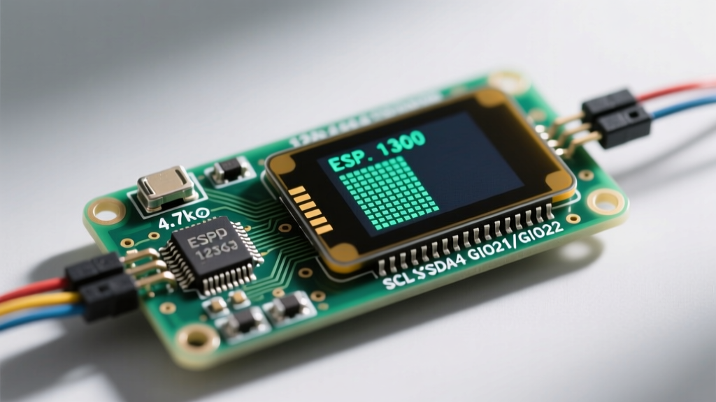
The BME280 is strictly a 3.3V device. Its absolute maximum rating on VCC and I/O pins is 3.6V. Connecting the SDA and SCL pins directly to a 5V Arduino Uno without a logic level shifter will slowly degrade the silicon. Initially, it will work, but within a few weeks, the I2C transceiver inside the BME280 will latch up, causing the entire Arduino I2C bus to hang. The Arduino I2C Communication Guide emphasizes the necessity of matching logic levels for reliable bus operation.
The Fix: Use a bidirectional logic level shifter based on the BSS138 MOSFET (available for ~$1.50). Do not rely on simple resistor voltage dividers for I2C lines; the pull-down resistors will interfere with the I2C open-drain architecture and ruin the signal rise times.
The Clone Silicon Trap: BMP280 vs BME280
A massive issue in the 2026 maker market is the proliferation of mislabeled sensors. You order a "BME280" for $2.50, wire it up, and get perfect temperature and pressure readings, but humidity returns NaN.
Expert Insight: The BMP280 measures Temperature and Pressure. The BME280 measures Temperature, Pressure, and Humidity. They share the exact same I2C addresses and similar register maps. Many unscrupulous manufacturers ship BMP280 silicon in BME280-labeled packaging.
How to verify your silicon: Look at the metal lid of the sensor chip. A genuine Bosch BME280 features a laser-etched 2D matrix lot code and a distinct, microscopic vent hole for the humidity polymer. If the lid is completely smooth or only has a simple alphanumeric string, it is likely a BMP280 or a clone. Genuine Adafruit or Pimoroni breakouts (priced around $14.95 to $19.95) guarantee authentic Bosch silicon.
Environmental Saturation and Condensation Recovery
Capacitive humidity sensors work by measuring the dielectric constant of a polymer layer that absorbs water vapor. If your Arduino temp humidity sensor is deployed in a greenhouse, bathroom, or outdoor enclosure where temperatures drop below the dew point, liquid water will condense directly onto the sensor element.
Once liquid water infiltrates the polymer matrix, the sensor will peg at 99-100% RH and may take weeks to dry out naturally, often resulting in permanent hysteresis (a persistent +5% offset).
The Datasheet Recovery Protocol
To rescue a saturated sensor, you must thermally drive the moisture out of the polymer without melting the plastic LGA package or desoldering the breakout components.
- Remove the sensor from the high-humidity environment.
- Place it in a convection oven or food dehydrator set to exactly 60°C (140°F).
- Bake for 2 to 3 hours. Do not exceed 85°C, as the LGA solder joints and plastic housing may degrade.
- Allow the sensor to cool slowly in a sealed container with fresh silica gel desiccant to prevent immediate re-condensation from ambient room humidity.
Step-by-Step Multimeter Diagnostics
When software fixes fail, move to hardware verification. Set your multimeter to the following modes to isolate the fault.
- VCC Verification: Measure between VCC and GND on the breakout board. For BME280, this must be 3.25V - 3.35V. If reading 4.8V+, your voltage regulator has failed or you wired it to 5V.
- I2C Pull-Up Check: Set the multimeter to resistance (Ω). Measure between SDA and VCC, then SCL and VCC (with power OFF). You should read between 2.2kΩ and 10kΩ. If it reads infinite (OL), your bus lacks pull-up resistors, and communication will fail.
- Data Line Continuity: For DHT22 setups, measure resistance between the Arduino digital pin and the sensor DATA pin. It should be <1Ω. If higher, check for cold solder joints or breadboard contact corrosion.
Upgrade Path: When to Abandon DHT for BME
If you are continuously battling DHT22 timing issues, it is time to redesign your PCB or breadboard layout. The Adafruit DHT Humidity Sensing Tutorial remains an excellent resource for basic setups, but for mission-critical data logging, the single-bus protocol is inherently flawed.
Migrating to a BME280 via I2C frees your microcontroller from microsecond bit-banging, allows you to daisy-chain multiple sensors on the same bus (using 0x76 and 0x77 addresses), and provides barometric pressure data for altitude compensation. While the BOM cost increases from ~$4.50 to ~$12.00, the reduction in firmware debugging time and the elimination of NaN errors makes the BME280 the definitive choice for serious environmental monitoring.