
Why You Cannot Drive a DC Motor Directly from an Arduino
A standard 130-size hobby DC motor typically draws between 150mA and 500mA under load, with stall currents easily exceeding 1A. The ATmega328P microcontroller on an Arduino Uno or Nano has an absolute maximum current rating of 40mA per I/O pin, and a recommended continuous limit of just 20mA. Attempting to wire a motor directly to a digital pin will instantly destroy the microcontroller's internal silicon due to thermal overstress.
To safely interface a motor, you must use a motor driver IC configured as an H-Bridge. This allows the low-current Arduino logic pins to control high-current power transistors that actually drive the motor. In this guide, we will cover the exact wiring, hardware selection, and the DC motor code for Arduino required to achieve precise bidirectional speed control using Pulse Width Modulation (PWM).
Hardware Selection: L298N vs. TB6612FNG
While the L298N has been the default hobbyist motor driver for a decade, modern robotics projects increasingly favor MOSFET-based drivers like the TB6612FNG. Below is a technical comparison to help you choose the right module for your 2026 build.
| Feature | L298N Module (BJT) | TB6612FNG Module (MOSFET) | DRV8871 Breakout |
|---|---|---|---|
| Topology | Bipolar Junction Transistor | N-Channel & P-Channel MOSFET | N-Channel MOSFET |
| Continuous Current | 2.0A per channel | 1.2A per channel | 3.6A single channel |
| Voltage Drop | ~1.4V to 2.0V (High heat) | ~0.5V (High efficiency) | ~0.4V |
| Logic Voltage | 5V (often requires jumper) | 2.7V to 5.5V | 3.3V to 5.5V |
| Typical Price | $3.00 - $5.00 | $4.50 - $7.00 | $5.00 - $9.00 |
Expert Insight: If you are powering your Arduino and motors from a 2S LiPo battery (7.4V nominal), the L298N's 2V voltage drop will leave only 5.4V for a motor rated at 6V, severely limiting torque. The TB6612FNG's 0.5V drop preserves your battery's voltage envelope. For detailed wiring on the modern alternative, refer to the SparkFun TB6612FNG Hookup Guide.
Wiring the L298N for Bidirectional Control
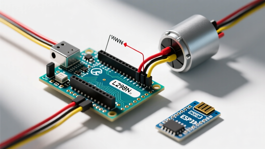
For this tutorial, we will use the ubiquitous L298N module due to its widespread availability and built-in 5V voltage regulator, which is highly convenient for beginners. You will need:
- Arduino Uno R3 or Nano
- L298N Motor Driver Module
- DC Gearmotor (e.g., TT motor, 3V-6V rated)
- External Power Supply (4x AA battery pack or 2S LiPo)
- 100µF Electrolytic Capacitor & 100nF Ceramic Capacitor
Step-by-Step Wiring Guide
- Motor Power (12V/VCC & GND): Connect your external battery pack's positive terminal to the L298N's
12Vscrew terminal. Connect the battery's negative terminal to the L298N'sGNDterminal. - Common Ground (Crucial): Run a jumper wire from the L298N's
GNDterminal directly to one of the Arduino'sGNDpins. Without a shared ground reference, the logic signals will float, causing erratic motor behavior. - Logic Pins (IN1 & IN2): Connect L298N
IN1to Arduino Digital Pin 7, andIN2to Digital Pin 8. These control the H-Bridge direction. - PWM Pin (ENA): Remove the physical jumper cap from the L298N's
ENApins. Connect theENApin to Arduino Digital Pin 9 (which supports hardware PWM). - Decoupling Capacitors: Solder a 100nF ceramic capacitor directly across the motor's physical terminals to suppress high-frequency EMI. Place a 100µF electrolytic capacitor across the main power rail on the breadboard to prevent voltage sags during motor startup.
The DC Motor Code for Arduino
Below is the complete, production-ready C++ code. It utilizes a custom function to abstract the H-Bridge logic, making your main loop clean and readable. We use the analogWrite() function to generate a PWM signal on the ENA pin, effectively simulating a variable voltage by rapidly switching the 5V logic signal on and off at a 490Hz frequency. For a deeper understanding of how the microcontroller handles duty cycles, consult the official Arduino analogWrite reference.
// Pin Definitions
const int IN1 = 7;    // Direction Pin 1
const int IN2 = 8;    // Direction Pin 2
const int ENA = 9;    // PWM Speed Control Pin

// Motor States
enum MotorDirection { FORWARD, BACKWARD, BRAKE };

void setup() {
  // Initialize digital pins as outputs
  pinMode(IN1, OUTPUT);
  pinMode(IN2, OUTPUT);
  pinMode(ENA, OUTPUT);

  // Ensure motor is stopped on boot
  setMotor(BRAKE, 0);

  Serial.begin(9600);
  Serial.println("Motor Controller Initialized.");
}

void loop() {
  // 1. Accelerate Forward
  Serial.println("Accelerating Forward...");
  for (int speed = 0; speed <= 255; speed += 5) {
    setMotor(FORWARD, speed);
    delay(50);
  }

  // 2. Cruise at max speed for 2 seconds
  delay(2000);

  // 3. Hard Brake
  Serial.println("Braking...");
  setMotor(BRAKE, 0);
  delay(1000);

  // 4. Reverse at 70% speed
  Serial.println("Reversing at 70%...");
  setMotor(BACKWARD, 178); // 255 * 0.70 = ~178
  delay(2000);

  // 5. Coast to stop (by setting speed to 0 without active braking)
  setMotor(FORWARD, 0);
  delay(3000); // Wait before repeating loop
}

// Core Motor Control Function
void setMotor(MotorDirection dir, int pwmSpeed) {
  // Constrain PWM to valid 8-bit range
  pwmSpeed = constrain(pwmSpeed, 0, 255);

  switch (dir) {
    case FORWARD:
      digitalWrite(IN1, HIGH);
      digitalWrite(IN2, LOW);
      analogWrite(ENA, pwmSpeed);
      break;

    case BACKWARD:
      digitalWrite(IN1, LOW);
      digitalWrite(IN2, HIGH);
      analogWrite(ENA, pwmSpeed);
      break;

    case BRAKE:
      // Active braking: shorting the motor terminals via the H-Bridge
      digitalWrite(IN1, HIGH);
      digitalWrite(IN2, HIGH);
      analogWrite(ENA, 0);
      break;
  }
}
Advanced Troubleshooting & Failure Modes
Even with correct wiring, embedded motor control presents unique electrical challenges. If your project is failing, check these specific edge cases:
1. Arduino Randomly Resets When Motor Starts
The Cause: DC motors draw massive inrush currents (stall current) when starting from a dead stop. If your motor and Arduino share the same power supply without adequate decoupling, the voltage rail will dip below the ATmega328P's brownout detection threshold (typically 4.3V for 5V boards), triggering a hardware reset.
The Fix: Never power high-torque motors directly from the Arduino's 5V pin. Use a dedicated battery pack for the motor driver, and ensure you have a bulk electrolytic capacitor (470µF or higher) placed physically close to the L298N power terminals to supply instantaneous current.
2. Motor Whines but Does Not Spin at Low PWM Values
The Cause: Standard Arduino PWM operates at ~490Hz. At low duty cycles (e.g., analogWrite(ENA, 30)), the voltage pulses are too short to overcome the motor's static friction and internal cogging torque, but the frequency is low enough to excite acoustic resonance in the motor casing.
The Fix: Implement a 'kickstart' routine in your code. Apply 100% PWM for 50 milliseconds to break static friction, then immediately drop down to your desired low-speed PWM value. Alternatively, modify the Arduino's hardware timers to increase the PWM frequency to 31kHz, moving the acoustic noise above human hearing.
3. L298N Overheating and Shutting Down
The Cause: The L298N relies on outdated BJT technology. At 2A of continuous current, it dissipates roughly 4 Watts of heat as waste. Without a massive heatsink and active cooling, the IC's internal thermal shutdown circuit will trip at 150°C.
The Fix: If your application requires continuous currents above 1A, abandon the L298N. Upgrade to a modern driver like the Arduino Motor Shield R3 (which uses the L298P but with better PCB copper pours for heat dissipation) or, ideally, a MOSFET-based driver like the TB6612FNG or DRV8871.
Handling Inductive Kickback
DC motors are highly inductive loads. When you abruptly cut power or change direction via the H-Bridge, the collapsing magnetic field inside the motor's coils generates a massive reverse voltage spike (Flyback voltage). This spike can easily exceed 50V, instantly punching through the Arduino's I/O protection diodes or the motor driver's transistors.
Fortunately, almost all commercial L298N and TB6612FNG breakout boards include built-in 1N4007 flyback diodes wired in reverse-bias across the motor outputs. However, if you are designing a custom PCB or wiring raw ICs, you must place four Schottky diodes (like the 1N5819) in an H-Bridge configuration around the motor outputs to safely route these inductive spikes back to the positive power rail.
Summary
Writing reliable DC motor code for Arduino requires more than just copying a sketch; it demands an understanding of the physical hardware limitations. By pairing a robust H-Bridge driver with isolated power rails, proper decoupling capacitors, and structured C++ logic, you ensure your robotics projects operate smoothly without suffering from brownouts or silicon damage. Always respect the current limits of your microcontroller, and let the motor driver handle the heavy lifting.