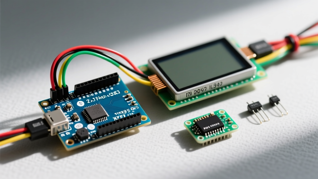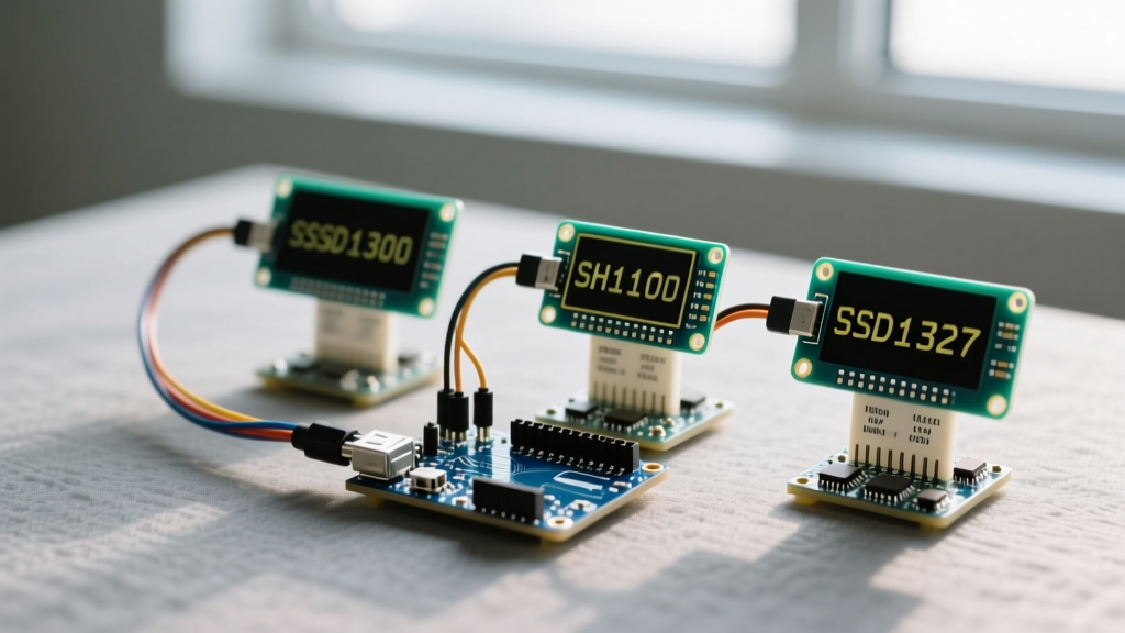

The Contenders: Decoding OLED Controllers
Integrating an OLED display with Arduino is a rite of passage for embedded systems developers. Unlike legacy 16x2 character LCDs, OLEDs offer deep blacks, microsecond response times, and crisp pixel-level control. However, the market is flooded with visually identical breakout boards hiding vastly different controller architectures. As of 2026, generic I2C OLED modules hover between $2.50 and $4.50, but selecting the wrong controller for your specific microcontroller can lead to severe SRAM bottlenecks, I2C bus collisions, and maddening pixel-offset bugs.
In this component comparison, we dissect the three dominant OLED controllers you will encounter: the ubiquitous SSD1306, the deceptive SH1106, and the grayscale-capable SSD1327. We will evaluate their memory footprints, hardware edge cases, and library compatibilities to help you engineer a bulletproof display interface.
Specification & Comparison Matrix
| Controller | Common Resolution | Interface | SRAM Footprint (Full Buffer) | Avg. Price (2026) | Best Application |
|---|---|---|---|---|---|
| SSD1306 | 128x64 / 128x32 | I2C / SPI | 1024 Bytes (128x64) | $2.80 - $4.00 | Standard UI, sensor readouts, battery-powered IoT |
| SH1106 | 132x64 (Displays 128x64) | I2C / SPI | 1056 Bytes | $3.50 - $5.50 | Larger 1.3" enclosures, basic text menus |
| SSD1327 | 128x128 | I2C / SPI | 8192 Bytes (4-bit Grayscale) | $7.00 - $12.00 | Advanced UI, dithering, progress bars, gauges |
SSD1306: The 0.96" Industry Standard
The SSD1306 is the undisputed workhorse of the maker community. Available primarily in 0.96-inch (128x64) and 0.91-inch (128x32) form factors, it boasts universal library support. The standard I2C address is 0x3C (when the SA0/DC pin is tied low) or 0x3D (tied high).
The ATmega328P SRAM Bottleneck
While the SSD1306 is easy to wire, its memory requirements are frequently overlooked by beginners. A 128x64 monochrome display requires a 1-bit-per-pixel framebuffer. This equates to (128 * 64) / 8 = 1024 bytes (1 KB) of SRAM. If you are using an Arduino Uno or Nano (based on the ATmega328P), you only have 2 KB of total SRAM. Allocating 50% of your microcontroller's memory purely to the display buffer leaves very little room for complex logic, WiFi stacks, or large sensor arrays.
Expert Tip: If you are constrained by SRAM, opt for a 128x32 OLED. The framebuffer drops to 512 bytes, freeing up critical memory for your application logic while still providing ample space for telemetry data.
SH1106: The 1.3" Clone Dilemma
The SH1106 controller is almost exclusively found in 1.3-inch OLED modules. Physically, it looks like a scaled-up SSD1306, and many third-party sellers falsely advertise it as such. However, the SH1106 is fundamentally different in its memory mapping architecture.
The 132x64 Memory Mapping Bug
The SH1106 silicon is designed to drive a 132x64 pixel matrix. Because 1.3" screens only physically wire up 128x64 pixels, the visible area is offset by 2 columns in the controller's internal RAM. If you attempt to drive an SH1106 module using a standard SSD1306 library, the library writes to columns 0 through 127. The display, however, renders columns 2 through 129. The result? Your UI is shifted off-screen by two pixels, and the right edge displays random static from uninitialized RAM.
The Fix: You must use a library explicitly designed to handle the SH1106 offset. The Adafruit_SH110X library or the U8g2 library (using the sh1106_128x64_noname constructor) automatically applies the 2-column write offset, ensuring perfect pixel alignment.
SSD1327: Stepping Up to 16-Level Grayscale
When monochrome limitations hinder your UI design, the 1.5-inch SSD1327 (128x128) enters the chat. Unlike the 1-bit monochrome controllers, the SSD1327 supports 4-bit depth, yielding 16 levels of grayscale. This allows for smooth dithering, anti-aliased fonts, and complex analog gauge overlays.
The trade-off is memory and processing overhead. A full 128x128 4-bit framebuffer requires 8 KB of SRAM—making it completely incompatible with standard 5V AVR Arduinos. To use the SSD1327 effectively, you must pair it with a 32-bit microcontroller like the ESP32, Raspberry Pi Pico (RP2040), or Arduino Nano 33 IoT, which possess 200+ KB of SRAM.
Critical Hardware Edge Cases & Wiring
Wiring an OLED display with Arduino goes far beyond connecting VCC to 5V and GND to GND. Real-world deployments require addressing electrical edge cases that generic tutorials ignore.
1. The Missing Pull-Up Resistor Trap
To shave pennies off the bill of materials, many generic $3 I2C OLED modules omit the mandatory 4.7kΩ pull-up resistors on the SDA and SCL lines. According to the official Arduino Wire reference, I2C requires an open-drain bus with external pull-ups. If the OLED is the only device on the bus, the ATmega328P's internal weak pull-ups (approx. 20kΩ) might barely sustain communication at 100kHz. However, if you add a BME280 sensor or DS3231 RTC to the same bus, the cumulative capacitance will degrade the signal edges, resulting in I2C timeouts and frozen displays. Always verify the presence of pull-ups with a multimeter, and solder external 4.7kΩ resistors if necessary.
2. 5V Logic vs. 3.3V OLED Degradation
The SSD1306 and SH1106 are 3.3V logic devices. Connecting them directly to a 5V Arduino Uno means you are feeding 5V into the I2C pins. While many modules survive this due to internal clamping diodes, continuous overvoltage stress will eventually degrade the silicon, leading to ghosting, dead pixels, or complete I2C bus lockups. For long-term reliability, use a bidirectional logic level shifter (like a BSS138-based module) or migrate to a 3.3V native microcontroller like the ESP32.
3. OLED Screen Burn-In
Like their full-sized television counterparts, micro-OLEDs are susceptible to phosphor degradation. If your Arduino project displays a static UI (e.g., a smart thermostat) 24/7, you will notice permanent burn-in within 3 to 6 months. Implement a software-based pixel-shift routine that moves the entire framebuffer by 1 or 2 pixels every few hours to distribute wear evenly across the organic diodes.
Library Showdown: Adafruit_GFX vs. U8g2
When programming an OLED display with Arduino, your choice of library dictates your project's performance and memory efficiency.
- Adafruit_SSD1306 / Adafruit_GFX: The most beginner-friendly option. It utilizes a full-framebuffer approach, meaning you can draw overlapping shapes and text without flickering. However, as noted, it consumes a massive 1KB of SRAM for a 128x64 screen. It is highly recommended for 32-bit boards but restrictive on AVR architectures.
- U8g2: The heavyweight champion of embedded displays. As detailed in the U8g2 GitHub Wiki, this library offers a 'Page Mode' (using the
u8g2_FirstPage()loop). Page mode renders the display in 8-row chunks, reducing the SRAM requirement from 1024 bytes down to roughly 64 bytes. The trade-off is that you cannot use overlapping transparent graphics, and the rendering loop must execute rapidly to prevent screen flicker.
Final Verdict: Which Should You Choose?
For 90% of hobbyist and prototyping applications, the 0.96" SSD1306 (I2C) remains the best OLED display with Arduino due to its unparalleled ecosystem support, low cost, and abundant documentation. If your project requires a larger physical footprint for readability across a room, step up to the 1.3" SH1106, but ensure your code accounts for the 2-column RAM offset. Finally, reserve the SSD1327 for advanced, 32-bit microcontroller projects where grayscale dithering and high-resolution UI elements are strictly necessary.
By understanding the underlying controller architecture and respecting I2C electrical specifications, you can transform a fragile $3 component into a robust, production-ready human-machine interface.