
The Reality of High-Torque DC Motor Arduino Projects
Most online tutorials demonstrating a dc motor arduino setup feature a tiny 3V toy motor spinning a plastic wheel on a desk. While educational, these guides fall apart the moment you attempt real-world automation. Building a heavy-duty actuator—such as an automated greenhouse roof vent opener, a solar tracker, or a motorized chicken coop door—requires moving significant mass. This demands high-torque 12V DC gear motors, which introduce severe electrical challenges: massive stall currents, destructive inductive kickback (back-EMF), and ground-loop brownouts that constantly reset your microcontroller.
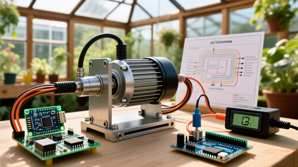
In this guide, we will design and wire a robust, high-torque linear actuator system using a 12V 775-series DC gear motor, an Arduino Uno (or ESP32), and an industrial-grade H-bridge. As of 2026, the availability of high-current MOSFET modules makes this safer and more efficient than ever, provided you respect the physics of inductive loads.
Selecting the Right H-Bridge: Beyond the L298N
The most common mistake DIYers make is pairing a high-torque motor with the ubiquitous L298N motor driver. The L298N relies on outdated Bipolar Junction Transistor (BJT) technology. It suffers from a massive internal voltage drop (up to 2.5V) and requires heavy heat sinking for continuous currents above 1.5A. If your 775 motor stalls under a heavy greenhouse window, the spike can easily exceed 10A, instantly melting the L298N's silicon.
For heavy-duty applications, you must use MOSFET-based drivers. Below is a comparison of popular drivers available on the market today:
| Driver Module | Technology | Continuous Current | Voltage Drop | Approx. Price (2026) | Best Use Case |
|---|---|---|---|---|---|
| L298N | BJT | 1.5A (with heatsink) | ~2.0V - 2.5V | $4 - $6 | Small toy motors, low-load prototypes |
| TB6612FNG | MOSFET | 1.2A per channel | ~0.5V | $9 - $12 | Mobile robots, lightweight RC servos |
| BTS7960 (43A Module) | MOSFET | 15A - 20A (active cooling) | < 0.1V | $14 - $18 | High-torque actuators, winches, heavy vents |
For our greenhouse actuator, the BTS7960 43A H-Bridge module is the undisputed winner. According to SparkFun's Motor Driver Selection Guide, matching the driver's continuous current rating to the motor's stall current is critical for preventing thermal runaway. The BTS7960 handles the 775 motor's 12A stall current effortlessly without dropping significant voltage or requiring a massive heatsink.
Wiring for Survival: Power, Grounding, and Flyback
Wiring a high-current dc motor arduino circuit requires strict separation between high-power and logic lines, while maintaining a common ground reference.
The Power Supply and Decoupling
Do not use cheap, unbranded wall warts. A sudden motor reversal or stall will cause a massive current draw that collapses the voltage rail, resetting your Arduino. Use an enclosed, industrial switching power supply like the Mean Well LRS-150-12 (12V, 12.5A, approx. $28).
To protect the Arduino from voltage sags, solder a 2200µF 25V electrolytic capacitor directly across the 12V input terminals on the BTS7960 module. This acts as a local energy reservoir, absorbing the initial inrush current when the motor starts.
The Inductive Kickback Problem
DC motors are massive inductors. When you cut power to a spinning motor, the collapsing magnetic field generates a high-voltage reverse spike (back-EMF) that can exceed 50V. While the BTS7960 has internal Zener diodes for basic clamping, real-world heavy actuators require external protection. Wire a 1N5408 (3A, 1000V) flyback diode in reverse bias across the motor terminals (cathode to positive, anode to negative). For an extra layer of safety, as detailed in Adafruit's motor control tutorials, adding a 0.1µF ceramic capacitor across the motor brushes will suppress high-frequency EMI that can otherwise corrupt your Arduino's analog sensor readings.
Wire Gauge and Connections
- Motor to H-Bridge: 14 AWG silicone stranded wire. Keep this as short as possible (under 12 inches) to minimize resistance and EMI radiation.
- Power Supply to H-Bridge: 12 AWG wire with ring terminals screwed tightly into the BTS7960's terminal blocks.
- Logic Pins (Arduino to H-Bridge): 22 AWG stranded wire.
- Common Ground: You MUST connect the Arduino GND, the BTS7960 B- (Logic Ground), and the 12V Power Supply negative terminal together. Without a common ground, the logic signals will float, causing erratic motor behavior.
Tuning PWM Frequencies for Silence and Efficiency
By default, the Arduino Uno's analogWrite() function operates at approximately 490Hz on most pins. When applied to a large, high-inductance motor like the 775, this low frequency causes the motor windings and internal laminations to physically vibrate at an audible pitch. This results in a loud, annoying whine and increases switching losses in the MOSFETs.
Expert Insight: To eliminate acoustic noise and improve thermal efficiency, you must push the Pulse Width Modulation (PWM) frequency above the human hearing range (20kHz). However, you must use pins controlled by Timer1 (Pins 9 and 10 on the Uno) to achieve this without breaking the millis() function, which relies on Timer0.
According to the official Arduino analog output documentation, manipulating the timer prescalers allows us to change the PWM frequency. Add the following line to your setup() function to set Timer1 to a prescaler of 1, yielding a PWM frequency of roughly 31.3kHz:
// Set Timer1 prescaler to 1 (approx 31.3kHz PWM on pins 9 & 10)
TCCR1B = TCCR1B & B11111000 | B00000001;
Real-World Code Implementation and Limit Switches
A greenhouse actuator must know when the window is fully open or fully closed to prevent the motor from stalling and drawing 12A continuously. We use industrial Omron D2F microswitches mounted at the physical limits of the actuator track, wired to the Arduino's digital inputs using INPUT_PULLUP.
const int RPWM = 9;  // Forward PWM (Timer1)
const int LPWM = 10; // Reverse PWM (Timer1)
const int R_EN = 8;  // Right Enable
const int L_EN = 7;  // Left Enable
const int LIMIT_OPEN = 2;  // NC microswitch
const int LIMIT_CLOSE = 3; // NC microswitch

void setup() {
  pinMode(RPWM, OUTPUT); pinMode(LPWM, OUTPUT);
  pinMode(R_EN, OUTPUT); pinMode(L_EN, OUTPUT);
  pinMode(LIMIT_OPEN, INPUT_PULLUP);
  pinMode(LIMIT_CLOSE, INPUT_PULLUP);

  TCCR1B = TCCR1B & B11111000 | B00000001; // 31kHz PWM

  digitalWrite(R_EN, HIGH);
  digitalWrite(L_EN, HIGH);
}

void openVent(int speed) {
  if (digitalRead(LIMIT_OPEN) == LOW) {
    analogWrite(RPWM, 0); // Limit hit, stop
    return;
  }
  analogWrite(LPWM, 0);
  analogWrite(RPWM, speed);
}

void closeVent(int speed) {
  if (digitalRead(LIMIT_CLOSE) == LOW) {
    analogWrite(LPWM, 0); // Limit hit, stop
    return;
  }
  analogWrite(RPWM, 0);
  analogWrite(LPWM, speed);
}

void stopMotor() {
  analogWrite(RPWM, 0);
  analogWrite(LPWM, 0);
}
Troubleshooting Common Actuator Failures
Even with perfect wiring, real-world environments introduce edge cases. Here is how to diagnose the most common high-torque dc motor arduino failures:
- Arduino Randomly Resetting: This is almost always a brownout caused by EMI or voltage sag. Ensure your 2200µF capacitor is properly soldered, and route your logic wires far away from the 14 AWG motor power cables to prevent inductive coupling.
- Motor Jerking at Low Speeds: High-torque gear motors require a minimum 'breakaway' voltage to overcome static friction. If your PWM value is below 60 (out of 255), the motor may stall and jerk. Implement a 'kickstart' routine in your code: apply
analogWrite(pin, 200)for 50 milliseconds before dropping to your desired low speed. - H-Bridge Overheating: If the BTS7960 gets too hot to touch, check your mechanical linkage. Misaligned tracks or binding hinges force the motor to draw continuous stall current. The electrical system can only compensate for so much mechanical inefficiency.
- Limit Switch Bounce: Mechanical microswitches can 'bounce' upon impact, sending multiple rapid HIGH/LOW signals that confuse the Arduino. Implement a 50-millisecond software debounce delay in your limit-checking logic, or place a 0.1µF capacitor across the switch terminals for hardware debouncing.
By respecting the electrical demands of high-torque motors and moving beyond beginner-tier components, your dc motor arduino actuator will operate reliably for years, surviving the harsh, humid, and electrically noisy environment of a real-world greenhouse.