
Understanding the SW-520D: Beyond the Mercury Switch
When designing anti-theft alarms, posture-correcting wearables, or interactive art installations, detecting orientation changes is critical. While MEMS accelerometers like the MPU-6050 offer multi-axis precision, they are often overkill for simple binary tilt detection. This is where the SW-520D rolling ball tilt sensor excels. Unlike older mercury tilt switches, which pose severe environmental and health hazards, the SW-520D uses a conductive free-moving metal ball resting between two electrodes.
When the sensor tilts past its activation angle (typically between 20° and 45°, depending on the specific manufacturing batch and orientation), the ball rolls away from the contact pins, breaking the circuit. According to Adafruit's sensor documentation, these rolling ball switches are highly sensitive to vibration and macro-movements, making them ideal for low-power, binary state-change detection.
2026 Bill of Materials and Pricing
Building a robust tilt-sensing circuit requires minimal components. Below is the current market pricing for hobbyist and prototyping quantities in 2026.
| Component | Model / Spec | Est. Price (USD) | Notes |
|---|---|---|---|
| Tilt Sensor | SW-520D (Pack of 50) | $4.50 - $6.00 | Buy in bulk; individual units are rarely sold. |
| Microcontroller | Arduino Uno R4 Minima | $19.99 | 32-bit ARM Cortex-M4; overkill but standard. |
| Resistor | 10kΩ (0.25W) | $0.02 | Optional if using internal pull-ups. |
| Capacitor | 0.1µF (100nF) Ceramic | $0.05 | Crucial for hardware debouncing. |
| Jumper Wires | M-F 28 AWG Silicone | $3.00 / 40-pack | Silicone insulation prevents melting near solder joints. |
Schematic and Wiring Guide
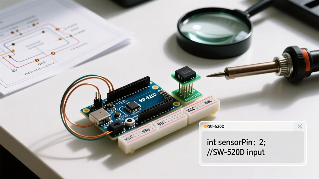
The SW-520D is a passive, non-polarized component. It acts exactly like a momentary pushbutton that is 'pressed' by gravity. You have two primary wiring topologies:
1. External Pull-Down Resistor
Wire one leg of the sensor to 5V and the other to a digital input pin (e.g., D2). Connect a 10kΩ resistor between D2 and GND. When tilted, the ball bridges the pins, pulling D2 HIGH. When upright, the resistor pulls D2 LOW.
2. Internal Pull-Up Resistor (Recommended)
Wire one leg to GND and the other to D2. By enabling the microcontroller's internal pull-up resistor, the pin reads HIGH when upright (circuit open) and LOW when tilted (circuit closed to GND). As noted in the official Arduino Digital Pins documentation, the internal pull-up is typically 20kΩ to 50kΩ, which perfectly limits current while providing a stable logic level, saving you a physical resistor and breadboard space.
The Hidden Enemy: Contact Bounce
Mechanical switches do not transition cleanly from open to closed. When the metal ball strikes the electrodes, it physically bounces, creating a rapid series of microsecond open/close spikes before settling. If your Arduino polls the pin during this window, a single tilt event will register as dozens of triggers.
As detailed in All About Circuits' guide on switch bouncing, this phenomenon can cause catastrophic logic errors in state machines. You must implement debouncing, either via software or hardware.
Hardware Debouncing: The RC Low-Pass Filter
For mission-critical applications where software latency is unacceptable, use an RC filter. Place a 0.1µF ceramic capacitor in parallel with the tilt sensor. Combined with a 10kΩ series resistor to the digital pin, you create a low-pass filter.
The Math: The time constant (τ) is calculated as τ = R × C.
τ = 10,000Ω × 0.0000001F = 0.001 seconds (1ms).
It takes roughly 3τ to 5τ (3-5ms) for the capacitor to charge/discharge, effectively smoothing out the 50µs - 500µs mechanical bounce spikes into a clean, sloped logic transition.
Non-Blocking Arduino C++ Implementation
Beginners often use the delay() function to ignore bounce, but this halts the microcontroller, preventing it from reading other sensors or updating displays. Below is a professional, non-blocking software debounce routine using millis().
const int TILT_PIN = 2;
const int LED_PIN = 13;

unsigned long lastDebounceTime = 0;
unsigned long debounceDelay = 50; // 50ms debounce window

int lastStableState = HIGH;
int currentReading;

void setup() {
  // Enable internal pull-up resistor
  pinMode(TILT_PIN, INPUT_PULLUP);
  pinMode(LED_PIN, OUTPUT);
  Serial.begin(115200);
  Serial.println("SW-520D Tilt Sensor Initialized.");
}

void loop() {
  currentReading = digitalRead(TILT_PIN);

  // If the switch changed, due to noise or pressing:
  if (currentReading != lastStableState) {
    lastDebounceTime = millis();
  }

  // Check if the state has been stable longer than the debounce delay
  if ((millis() - lastDebounceTime) > debounceDelay) {
    if (currentReading != lastStableState) {
      lastStableState = currentReading;

      // Action triggers only on the confirmed state change
      if (lastStableState == LOW) {
        Serial.println("ALERT: Device Tilted!");
        digitalWrite(LED_PIN, HIGH);
      } else {
        Serial.println("Device Upright.");
        digitalWrite(LED_PIN, LOW);
      }
    }
  }
}
Decision Matrix: Tilt Switch vs. MEMS Accelerometer
Choosing between an SW-520D and a 6-axis IMU (like the MPU-6050 or BNO086) depends entirely on your project's data requirements.
| Feature | SW-520D Tilt Sensor | MPU-6050 (MEMS IMU) |
|---|---|---|
| Cost | $0.10 per unit | $1.50 - $3.00 per module |
| Output Data | Binary (Tilted / Upright) | Continuous (X, Y, Z Accel & Gyro) |
| Power Draw | 0mA (Open circuit when upright) | ~3mA active (Requires I2C polling) |
| Code Complexity | Extremely Low (Digital Read) | High (I2C, DMP, Quaternion math) |
| Best Use Case | Anti-theft triggers, sleep/wake switches | Drones, balancing robots, gesture tracking |
Common Failure Modes and Troubleshooting
Despite their simplicity, SW-520D sensors present unique edge cases in the field. Use this matrix to diagnose erratic behavior.
| Symptom | Root Cause | Solution |
|---|---|---|
| False triggers from loud noises or footsteps | Acoustic vibration causing the lightweight ball to micro-bounce. | Wrap the sensor in heat-shrink tubing with a dab of hot glue to dampen high-frequency acoustic resonance. |
| Sensor fails to trigger when tilted slowly | Oxidation on cheap, non-gold-plated internal contacts. | Run a 5V, 20mA 'wetting' current through the closed switch to burn off oxidation, or source from premium suppliers like E-Switch. |
| Pin reads 'floating' or random noise | Missing pull-up/pull-down resistor. | Ensure INPUT_PULLUP is declared in setup(), or wire an external 10kΩ resistor. |
| Multiple rapid triggers in Serial Monitor | Switch contact bounce. | Increase debounceDelay to 75ms or add a 0.1µF hardware capacitor. |
Final Integration Tips
When soldering the SW-520D, keep the iron temperature below 350°C and limit contact time to 3 seconds per pin. The internal plastic cavity can warp if overheated, permanently trapping the metal ball or altering the activation angle. For PCB integration, consider mounting the sensor on a breakaway riser to ensure the tilt angle aligns perfectly with your enclosure's center of gravity.