
The Reality of Ultrasonic Sensing in 2026
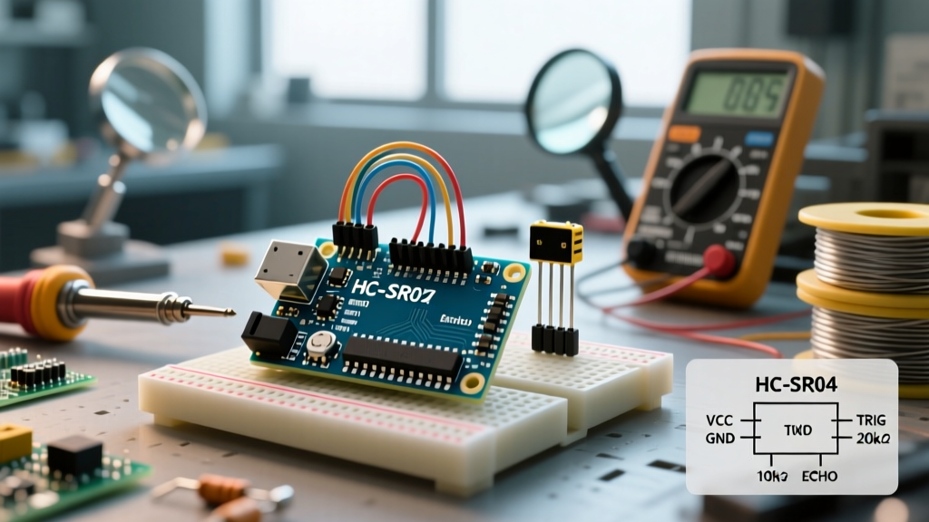
If you have spent more than an hour in the DIY electronics space, you have inevitably wired an HC-SR04 to an Arduino. It is the quintessential rite of passage. However, as projects mature from indoor desktop prototypes to outdoor robotics or 3.3V microcontroller ecosystems, the standard HC-SR04 falls short. It fails in high humidity, lacks 3.3V logic tolerance, and suffers from acoustic crosstalk in multi-sensor arrays.
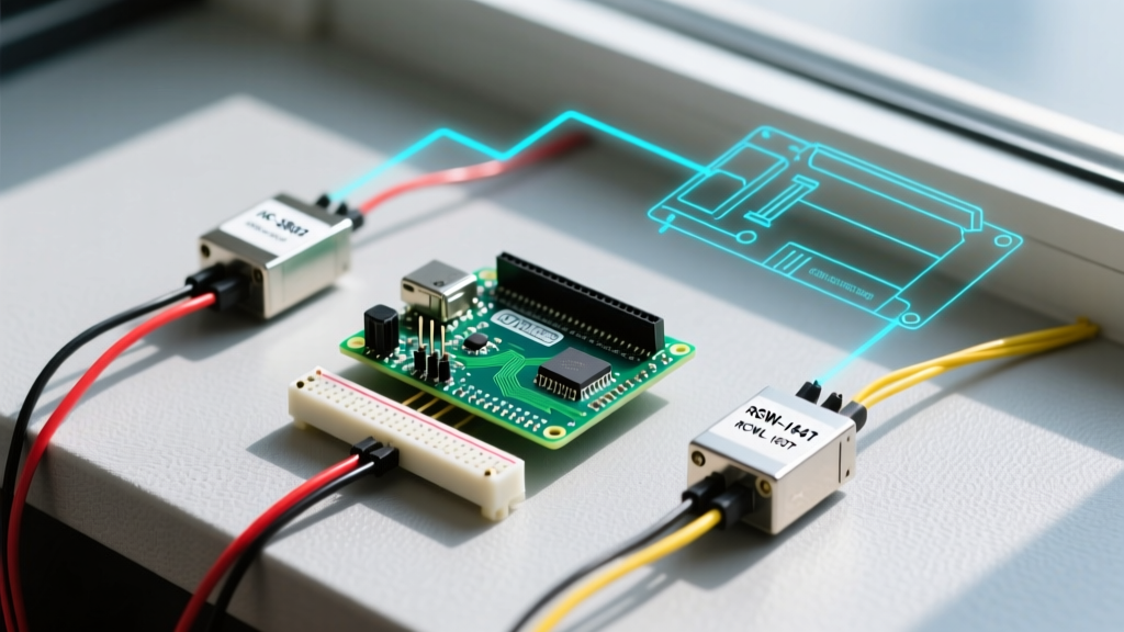
This guide moves beyond the basic Arduino Ping tutorial. We will compare the three most dominant ultrasonic modules on the 2026 market—the HC-SR04, the waterproof JSN-SR04T, and the 3.3V-native RCWL-1601—and provide the exact Arduino with ultrasonic sensor code required to handle their unique hardware quirks, blind spots, and timing anomalies.
Hardware Comparison: The 2026 Market Contenders
Before writing a single line of C++, you must understand the physical limitations of your transducer. The speed of sound is constant, but the transceiver circuitry dictates your code's timeout values and blind spot handling.
| Feature | HC-SR04 (Standard) | JSN-SR04T (Waterproof) | RCWL-1601 (3.3V/I2C) | MaxBotix MB1010 (Premium) |
|---|---|---|---|---|
| 2026 Street Price | $1.20 | $4.50 | $2.80 | $29.95 |
| Logic Voltage | 5V Only | 5V Only | 3.3V - 5.5V | 2.5V - 5.5V |
| Blind Spot | ~2 cm | ~20 cm | ~2 cm | 0 cm (Reads to surface) |
| Max Range | 400 cm | 450 cm | 450 cm | 645 cm |
| Interface | Trigger/Echo | Trigger/Echo | Trig/Echo, I2C, UART | Analog, PWM, Serial |
The Baseline: Optimized HC-SR04 Code
The native pulseIn() function in Arduino is blocking and notoriously inefficient. If an echo is never received (e.g., the sound wave hits a soft, angled surface and scatters), pulseIn() will hang your main loop for up to 38 milliseconds per reading. In a 50Hz robot control loop, this latency is catastrophic.
The industry standard solution is the NewPing Library, which utilizes timer interrupts to prevent blocking and automatically handles out-of-range timeouts.
#include <NewPing.h>

#define TRIGGER_PIN  9
#define ECHO_PIN     10
#define MAX_DISTANCE 400 // HC-SR04 max range

NewPing sonar(TRIGGER_PIN, ECHO_PIN, MAX_DISTANCE);

void setup() {
  Serial.begin(115200);
}

void loop() {
  // ping_cm() handles the 58.2 microsecond per cm math internally
  unsigned int distance = sonar.ping_cm();

  if (distance == 0) {
    Serial.println("Out of range or scattered echo");
  } else {
    Serial.print("Distance: ");
    Serial.print(distance);
    Serial.println(" cm");
  }
  delay(35); // Minimum 35ms delay to prevent acoustic self-interference
}
Adapting Code for the JSN-SR04T (Waterproof)
The JSN-SR04T separates the transducer from the PCB via a 2.5-meter cable, making it ideal for liquid level sensing or outdoor robotics. However, its physical design introduces a massive 20cm blind spot due to the acoustic dampening ring around the sealed probe. Furthermore, its internal comparator circuit requires a slightly longer timeout threshold than the HC-SR04.
Crucial JSN-SR04T Code Modifications
If you use the standard HC-SR04 code on a JSN-SR04T, objects placed within 20cm will return erratic values or false positives due to internal acoustic ringing within the probe housing. You must implement a software filter to reject readings below the physical blind spot.
#include <NewPing.h>

#define TRIGGER_PIN  9
#define ECHO_PIN     10
#define MAX_DISTANCE 450
#define BLIND_SPOT   22 // JSN-SR04T physical ringing zone

NewPing sonar(TRIGGER_PIN, ECHO_PIN, MAX_DISTANCE);

void loop() {
  unsigned int raw_distance = sonar.ping_cm();

  // Filter out acoustic ringing false positives
  if (raw_distance > 0 && raw_distance < BLIND_SPOT) {
    Serial.println("Target inside blind spot (Invalid)");
  } else if (raw_distance == 0) {
    Serial.println("Out of Range");
  } else {
    Serial.print("Valid Distance: ");
    Serial.print(raw_distance);
    Serial.println(" cm");
  }
  delay(50); // JSN requires slightly longer reset time between pings
}
Hardware Warning: The JSN-SR04T operates strictly at 5V. If you are using an ESP32 or Arduino Due, you must use a bidirectional logic level shifter (like the BSS138) on the Echo pin, or you will fry your 3.3V GPIO.
The 3.3V Bypass: RCWL-1601 via I2C
The RCWL-1601 is the modern engineer's answer to the 5V limitation. It features an onboard voltage regulator and level-shifting circuitry, allowing direct connection to 3.3V microcontrollers. But its true superpower is its multimodal interface. While it supports standard Trigger/Echo, it also supports I2C and UART.
Using I2C mode entirely eliminates the need for pulseIn() or timer interrupts, freeing up your MCU's resources and completely bypassing timing jitter issues common in RTOS environments.
Wiring for I2C Mode
- VCC: 3.3V or 5V
- GND: GND
- SDA: Connect to the Trigger pin (Pull high via 10kΩ resistor to VCC)
- SCL: Connect to the Echo pin (Pull high via 10kΩ resistor to VCC)
RCWL-1601 I2C Arduino Code
#include <Wire.h>

#define RCWL_I2C_ADDRESS 0x57 // Default I2C address

void setup() {
  Wire.begin();
  Serial.begin(115200);
}

void loop() {
  Wire.beginTransmission(RCWL_I2C_ADDRESS);
  Wire.write(0x01); // Send trigger command
  Wire.endTransmission();

  delayMicroseconds(120); // Wait for measurement cycle

  Wire.requestFrom(RCWL_I2C_ADDRESS, 3);
  if (Wire.available() == 3) {
    byte msb = Wire.read();
    byte lsb = Wire.read();
    byte checksum = Wire.read();

    if ((msb + lsb) == checksum) {
      int distance = (msb << 8) | lsb;
      Serial.print("I2C Distance: ");
      Serial.print(distance / 10.0); // Returns in mm, convert to cm
      Serial.println(" cm");
    }
  }
  delay(40);
}
Advanced Edge Cases: Temperature & Crosstalk
Professional deployments cannot ignore the physics of acoustics. The standard Arduino code assumes the speed of sound is exactly 343 m/s. This is only true at 20°C. At 0°C, the speed drops to 331 m/s. If your robot operates in an unheated warehouse, a 200cm distance reading will carry a 7.2 cm error purely due to temperature.
Implementing Real-Time Temperature Compensation
To fix this, integrate a DS18B20 temperature sensor and adjust the ping math dynamically:
float getTempCompensatedDistance(float tempC, unsigned long echoTimeUs) {
  // Speed of sound in cm/us based on temperature
  float speedOfSound = (331.3 + 0.606 * tempC) / 10000.0;
  float distance = (echoTimeUs / 2.0) * speedOfSound;
  return distance;
}
Solving Acoustic Crosstalk in Arrays
If you mount three HC-SR04 sensors on a rover's bumper, firing them simultaneously will result in Sensor A reading the echo from Sensor B's ping. This is called acoustic crosstalk. Never use parallel pinging. You must implement a sequential polling array with a minimum 35ms dead-time between each sensor firing to allow the 40kHz burst to dissipate entirely from the environment.
Summary Verdict: Which Sensor Should You Code For?
- Choose the HC-SR04 if you are building an indoor, 5V Arduino Uno project on a strict budget ($1.20) and can tolerate the blocking nature of basic code.
- Choose the JSN-SR04T for liquid tanks, outdoor weather stations, or dusty environments, but remember to code a 22cm software blind-spot filter and use a 50ms polling delay.
- Choose the RCWL-1601 if you are migrating to ESP32, Arduino Nano 33 IoT, or any 3.3V architecture. Utilizing its I2C mode yields the cleanest, non-blocking code architecture available in the sub-$5 tier.