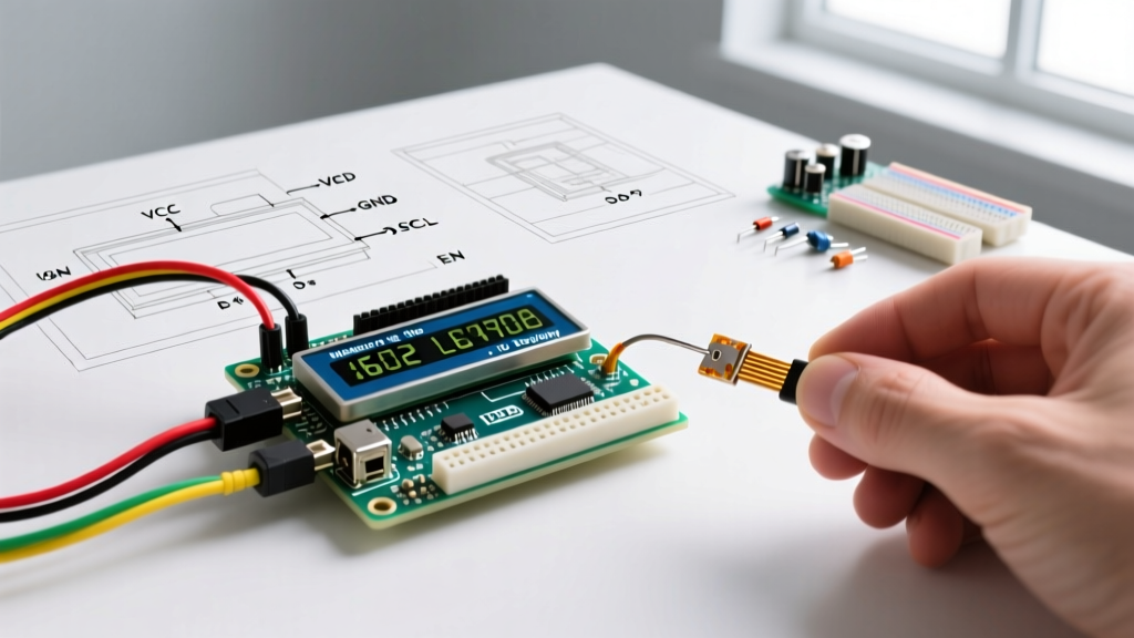

The HD44780 Architecture in 2026
Despite the proliferation of OLEDs and TFT touchscreens, the Arduino 1602A LCD display remains a cornerstone of embedded systems prototyping and industrial control panels. Based on the ubiquitous Hitachi HD44780 controller (or modern equivalents like the SPLC780D), this 16-column by 2-row character display offers unmatched reliability, wide temperature tolerance, and simple memory-mapped text rendering.
As of 2026, standard parallel 1602A modules (like the QC1602A or LCM1602A) cost between $2.50 and $4.00, while I2C-equipped variants range from $4.50 to $7.00. However, the simplicity of the hardware belies the complexity of its integration. Incorrect contrast biasing, I2C address conflicts, and outdated library usage remain the primary failure points for engineers and makers. This guide provides a definitive, expert-level breakdown of wiring, code implementation, and edge-case troubleshooting.
Interface Showdown: Parallel vs. I2C
The 1602A natively supports an 8-bit or 4-bit parallel interface. To save GPIO pins, the industry standard shifted to using 4-bit mode. Alternatively, I2C backpacks (utilizing PCF8574 I/O expanders) compress the interface down to just two data wires. Below is a technical comparison to help you select the right topology for your MCU.
| Feature | 4-Bit Parallel Mode | I2C Backpack (PCF8574) |
|---|---|---|
| MCU Pins Required | 6 (RS, EN, D4, D5, D6, D7) | 2 (SDA, SCL) |
| Wiring Complexity | High (requires contrast pot & backlight resistor) | Low (built-in contrast pot & backlight control) |
| Data Transfer Speed | Faster (direct GPIO toggling) | Slower (I2C bus overhead at 100kHz/400kHz) |
| Address Conflicts | None | Possible (0x27 vs 0x3F hardware variants) |
| Best Use Case | High-speed data logging, pin-rich MCUs (Mega2560) | ESP32/IoT nodes, pin-constrained MCUs (Attiny85) |
Hardware Wiring: Parallel Mode (4-Bit)
When wiring the 1602A in 4-bit parallel mode, you utilize pins 4 through 9 on a standard Arduino Uno. The R/W (Read/Write) pin on the LCD (Pin 5) must be tied directly to GND to force the display into write-only mode, as reading the busy flag is rarely necessary for standard text output.
The Contrast (V0) and Backlight Traps
Most tutorials blindly recommend a 10kΩ potentiometer for the V0 contrast pin (LCD Pin 3). While functional, this is an outdated approach that wastes board space and draws unnecessary current.
Expert Insight: At a 5V VDD supply, the internal LCD voltage generator produces a Vout (Pin 18) of approximately -1.5V to -2.0V. To achieve optimal contrast, the V0 pin requires a voltage between 0.5V and 1.0V relative to GND. Instead of a bulky potentiometer, solder a fixed 1kΩ or 2.2kΩ resistor between V0 and GND. This provides a permanent, perfect contrast for 5V logic systems without the mechanical drift of a cheap potentiometer.
Similarly, the backlight pins (Anode/Pin 15 and Cathode/Pin 16) are a frequent source of hardware failure. Some 1602A PCBs include a surface-mount current-limiting resistor on the back; others do not. If your module lacks this resistor, applying 5V directly to Pin 15 will instantly burn out the LED array. Always measure the resistance between Pin 15 and the LED trace. If it reads near 0Ω, insert an external 10Ω to 47Ω current-limiting resistor in series with the 5V supply.
Hardware Wiring: I2C Backpack & Address Conflicts
I2C backpacks solder onto the 16-pin header of the 1602A, utilizing a PCF8574 or PCF8574A I/O expander chip. The most common point of failure here is assuming the I2C address. According to the official Texas Instruments PCF8574 datasheet, the base address for the standard PCF8574 is 0x20, while the PCF8574A variant starts at 0x38.
- Standard PCF8574 Backpacks: Typically resolve to
0x27(with all three A0-A2 jumpers open/high). - PCF8574A Backpacks: Typically resolve to
0x3F(with all three jumpers open/high).
If you are migrating a project from an Uno to an ESP32 or Raspberry Pi Pico, remember that the I2C pinout changes. On the ESP32, default SDA is GPIO 21 and SCL is GPIO 22. Always use 4.7kΩ pull-up resistors on the SDA and SCL lines if your backpack lacks them, especially when running the bus at 400kHz Fast Mode.
Modern Code Implementation (C++)
Historically, developers relied on the legacy LiquidCrystal and LiquidCrystal_I2C libraries. However, the LiquidCrystal_I2C library is notorious for failing when backpack manufacturers alter the internal pin mapping (e.g., swapping the Enable and Register Select pins).
In 2026, the undisputed industry standard is the hd44780 library by Bill Perry. It automatically scans the I2C bus, identifies the correct address, and auto-detects the internal PCF8574-to-HD44780 pin mapping, eliminating 90% of initialization headaches.
Auto-Detect I2C Code Example
Install the hd44780 library via the Arduino IDE Library Manager. Select the I2Cexp diagnostic sketch to verify your hardware, then use the following production-ready boilerplate:
#include <Wire.h>
#include <hd44780.h>
#include <hd44780ioClass/hd44780_I2Cexp.h>

// Automatically detects I2C address and pin mapping
hd44780_I2Cexp lcd;

void setup() {
  // Initialize LCD with 16 columns and 2 rows
  int status = lcd.begin(16, 2);

  if (status != 0) {
    // If initialization fails, blink the onboard LED to signal error
    hd44780::fatalError(status);
  }

  lcd.print("ElectricalFlux");
  lcd.setCursor(0, 1);
  lcd.print("1602A I2C Ready");
}

void loop() {
  // Update a sensor value every second
  lcd.setCursor(13, 1);
  lcd.print(millis() / 1000);
  delay(1000);
}
Expert Troubleshooting Matrix
When your 1602A fails to render text, use this diagnostic matrix to isolate the fault domain. Do not immediately assume the LCD is defective; 95% of failures are electrical or configuration-based.
| Visual Symptom | Root Cause | Corrective Action |
|---|---|---|
| Single row of solid white/black blocks | Initialization failure. The MCU sent data before the LCD internal voltage stabilized, or the RW pin is floating. | Ensure RW is tied to GND. Add a delay(500); before lcd.begin() in setup to allow VDD to stabilize. |
| Backlight ON, screen completely blank | V0 contrast voltage is too close to VDD (5V). The liquid crystals are fully untwisted, blocking light. | Adjust the contrast potentiometer down, or verify your fixed resistor to GND is not missing/open. |
| 'Ghost' or faint overlapping characters | V0 contrast voltage is too low (too close to GND). The liquid crystals are over-twisted. | Increase V0 voltage. If using a fixed resistor, swap the 1kΩ for a 2.2kΩ or 4.7kΩ. |
| Garbage characters / random symbols | I2C pin mapping mismatch (if using legacy libraries) or I2C bus noise causing dropped bits. | Switch to the hd44780 library. Add 4.7kΩ pull-up resistors to SDA/SCL lines. |
| Text shifts right by one character | Writing to the LCD before calling lcd.clear() or failing to reset cursor position in the loop. |
Use lcd.setCursor(0, 0) before overwriting text, or pad strings with spaces to overwrite old data. |
Frequently Asked Questions
Can I run a 5V 1602A LCD directly from a 3.3V ESP32 or Raspberry Pi Pico?
Technically, the HD44780 controller requires a minimum of 4.5V for reliable logic high thresholds and internal charge pump operation. While some modern clones will boot at 3.3V, the contrast will be severely degraded, and the backlight will be dim. Best Practice: Power the LCD VDD and Backlight Anode from the 5V USB/VIN rail of your ESP32, and use a bidirectional logic level shifter (like the BSS138 MOSFET circuit) for the I2C SDA/SCL lines to protect the 3.3V MCU GPIOs.
Why does my I2C backpack get hot to the touch?
The PCF8574 chip on the backpack is sinking current for the LCD backlight. Standard 1602A backlights draw between 20mA and 40mA. The PCF8574 has a maximum continuous sink current of roughly 25mA per pin. If your specific LCD draws 40mA, the chip is operating beyond its safe operating area (SOA). To fix this, locate the jumper on the backpack labeled 'LED' or 'Backlight', remove the jumper, and wire the backlight Anode directly to the 5V supply through an appropriate transistor or MOSFET controlled by a separate MCU PWM pin.
How do I create custom characters on the 1602A?
The HD44780 features a Character Generator RAM (CGRAM) that holds up to 8 custom 5x8 pixel characters. You can define these using byte arrays in your C++ code and load them using the lcd.createChar() function during the setup() phase. Remember that you must switch back to the standard DDRAM (using lcd.setCursor()) before attempting to print the custom character to the screen.