
Decoding the Black Box: Inside the Standard 5V Relay Module
Almost every beginner electronics kit includes a blue 5V relay module for Arduino. While it is often treated as a simple 'black box' that clicks when a pin goes HIGH, understanding its internal datasheet and support circuitry is the difference between a reliable automation project and a fried microcontroller. In this datasheet explainer, we dissect the ubiquitous SRD-05VDC-SL-C relay and the module's surrounding components to reveal exact specifications, hidden isolation features, and real-world load limits.
The Core Component: SRD-05VDC-SL-C Datasheet Breakdown
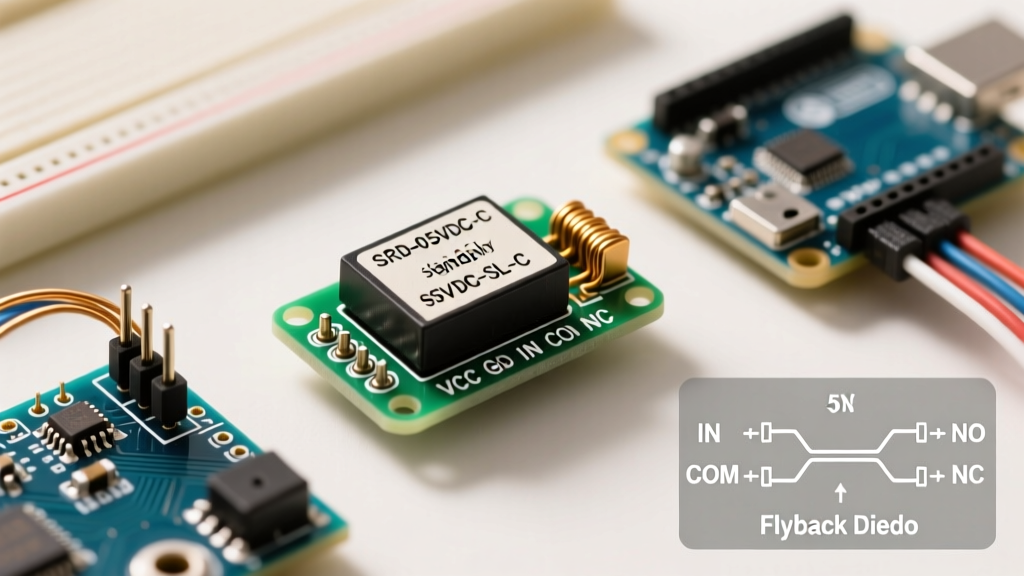
The heart of the standard 5V relay module is the Songle (or equivalent clone) SRD-05VDC-SL-C. This is a Single Pole Double Throw (SPDT) electromechanical relay. Below are the critical electrical characteristics extracted directly from the manufacturer datasheet.
| Parameter | Specification | Practical Implication for Arduino |
|---|---|---|
| Coil Voltage | 5V DC | Requires a stable 5V supply; 3.3V logic boards cannot drive the coil directly. |
| Coil Resistance | 70 Ω | Draws approximately 71.4 mA when energized. Exceeds standard Arduino GPIO limits (20-40mA). |
| Pick-up Voltage | 3.75 V DC (75% of nominal) | Will reliably engage as long as the 5V rail doesn't sag below 3.75V under load. |
| Drop-out Voltage | 0.5 V DC (10% of nominal) | Ensures the relay fully disengages when the signal drops, preventing contact welding. |
| Max Contact Rating (Resistive) | 10A @ 250VAC / 30VDC | Strictly for resistive loads (heaters, incandescent bulbs). See derating section below for motors. |
| Operate Time | 10 ms | Introduces a slight delay; not suitable for high-frequency PWM switching. |
Module Circuitry Explained: Beyond the Relay Coil
You cannot connect an Arduino GPIO pin directly to the relay coil. The 71.4 mA current draw would damage the microcontroller's ATmega328P or ESP32 silicon. The 5V relay module solves this with a three-stage support circuit.
1. The Optocoupler (PC817 / EL817)
High-quality modules feature a PC817 optocoupler. When your Arduino sends a LOW signal to the IN pin, it illuminates an internal infrared LED. This light triggers a phototransistor on the isolated side, which then drives the relay. This provides galvanic isolation, protecting your 50-dollar microcontroller from 120V/240V AC spikes.
2. The Switching Transistor (S8050 NPN)
The phototransistor inside the optocoupler cannot handle the 71.4 mA coil current alone. Therefore, its output drives the base of an S8050 NPN bipolar junction transistor (BJT). This BJT acts as a heavy-duty switch, safely routing the 71.4 mA from the 5V rail through the relay coil to ground.
3. The Flyback Diode (1N4148)
Relay coils are inductors. When the transistor switches off, the collapsing magnetic field generates a massive reverse voltage spike (back-EMF) that can instantly destroy the S8050 transistor. The module includes a 1N4148 signal diode wired in reverse parallel across the coil to safely dissipate this spike. As noted in All About Circuits' guide on relay design, omitting this diode guarantees premature component failure.
The JD-VCC Jumper: Unlocking True Optical Isolation
This is the most misunderstood feature of the 5V relay module for Arduino. On the module's VCC and JD-VCC pins, there is a small plastic jumper cap. By default, it bridges the two pins, powering both the optocoupler LED side and the relay coil side from the same 5V source.
Expert Configuration: To achieve true galvanic isolation, remove the JD-VCC jumper. Connect your Arduino's 5V to the VCC pin (powering only the optocoupler input side), and connect a separate, dedicated 5V power supply to the JD-VCC and GND pins (powering the relay coil). This ensures high-voltage noise from the AC load cannot travel back through the relay coil's ground plane into your microcontroller.
Real-World Load Derating: The 10A Myth
The datasheet boldly claims a 10A switching capacity at 250VAC. However, this rating applies only to purely resistive loads. If you use this module to switch inductive loads like AC motors, compressors, or solenoids, the initial inrush current and the inductive kickback upon opening will cause severe contact arcing.
According to Components101's relay module documentation, failing to derate the relay for inductive loads will cause the internal contacts to weld together in a closed position, creating a severe fire hazard. Follow these real-world derating guidelines:
- Resistive Loads (Heaters, Incandescent Lamps): Safe up to 8A continuous (derated 20% from 10A max for thermal headroom).
- Inductive Loads (AC Motors, Pumps, Transformers): Derate to 20% of max rating. Do not exceed 2A continuous.
- Capacitive Loads (LED Drivers, Switching Power Supplies): Derate to 30%. Limit to 3A to handle inrush charging currents.
Wiring the 5V Relay Module to Arduino
For a standard non-isolated setup (jumper intact), the wiring is straightforward. For detailed schematic references, consult the official Arduino relay documentation.
Low-Side Control Wiring (Active LOW)
Most commercial 5V relay modules are 'Active LOW', meaning the relay engages when the IN pin is pulled to GND (0V).
- Connect VCC on the module to the 5V pin on the Arduino.
- Connect GND on the module to the GND pin on the Arduino.
- Connect IN on the module to a digital pin (e.g., Pin 8) on the Arduino.
- Connect your high-voltage load to the COM (Common) and NO (Normally Open) screw terminals.
Basic Arduino Control Code
const int RELAY_PIN = 8;

void setup() {
  pinMode(RELAY_PIN, OUTPUT);
  digitalWrite(RELAY_PIN, HIGH); // Start with relay OFF (Active LOW)
}

void loop() {
  digitalWrite(RELAY_PIN, LOW);  // Turn relay ON
  delay(5000);                   // Keep ON for 5 seconds
  digitalWrite(RELAY_PIN, HIGH); // Turn relay OFF
  delay(5000);                   // Keep OFF for 5 seconds
}
Troubleshooting Matrix: Common Failure Modes
When your 5V relay module for Arduino fails to operate correctly, use this diagnostic matrix to identify the root cause without blindly replacing parts.
| Symptom | Probable Cause | Diagnostic & Fix |
|---|---|---|
| Module LED turns on, relay clicks, but load doesn't power. | Loose screw terminal or wrong contact used. | Verify wiring. Ensure load is on COM and NO (Normally Open), not NC (Normally Closed). |
| Relay chatters or clicks rapidly. | Insufficient current from Arduino 5V rail. | The Arduino's onboard 5V regulator is browning out under the 71mA load. Power the module VCC from an external 5V supply. |
| Relay stays ON permanently after first trigger. | Contacts welded due to inductive arcing. | The load exceeded the 2A inductive limit. Replace the relay and add an RC snubber circuit across the load. |
| Arduino resets when relay clicks. | Back-EMF noise coupling into logic. | Remove JD-VCC jumper and use a separate power supply for the relay coil to isolate the noise. |
Final Thoughts on Peripheral Integration
The 5V relay module for Arduino remains a staple in DIY automation because it bridges the gap between low-voltage logic and high-voltage actuation. However, treating it as a simple switch ignores the complex electromechanical physics at play. By respecting the SRD-05VDC-SL-C datasheet limits, properly configuring the JD-VCC isolation jumper, and strictly derating for inductive loads, you can build peripheral interfaces that are both safe and highly reliable for years of continuous operation.