
The Hidden Bottleneck: Why Drivers Dictate Your Display Choice
When selecting a display for Arduino projects, most makers focus on physical dimensions, resolution, and interface type (I2C vs. SPI). However, in 2026, the true bottleneck in embedded UI design is the software driver. A poorly optimized library can consume 80% of your microcontroller's SRAM, cause SPI bus collisions, or introduce severe rendering latency. Whether you are wiring up a $4 monochrome OLED or a $15 color TFT, understanding the underlying library architecture is critical for stable, high-performance peripheral integration.
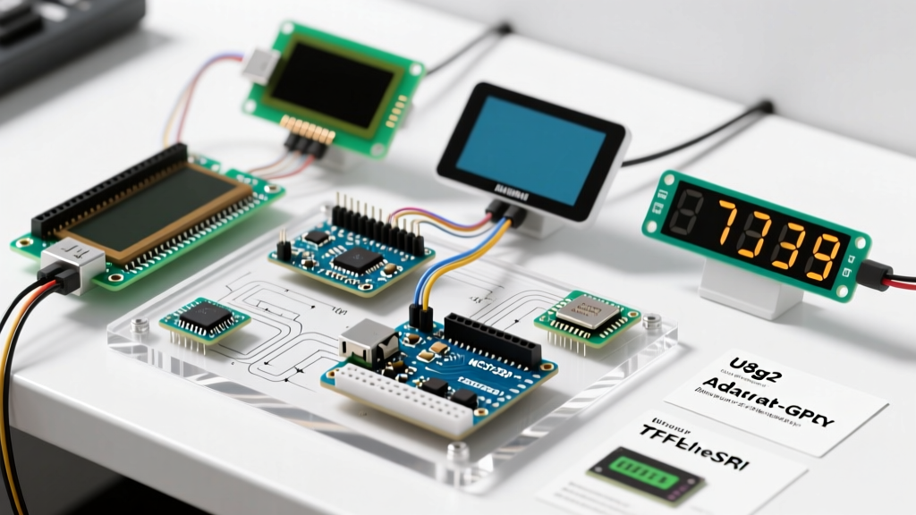
This guide dissects the three dominant display driver ecosystems—U8g2, Adafruit_GFX, and TFT_eSPI—providing actionable data on memory footprints, rendering speeds, and specific hardware edge cases for AVR, ESP32, and the newer Arduino Uno R4 Minima.
Core Library Matrix: Memory, Speed, and Use Cases
Before committing to a specific display for Arduino, evaluate the software overhead. The table below benchmarks the three primary libraries on a standard 128x64 OLED and a 240x240 TFT, compiled for an ATmega328P (2KB SRAM) and an ESP32-S3 (512KB SRAM).
| Library | Target Hardware | SRAM Overhead (128x64) | SPI/I2C Bus Load | Best Application |
|---|---|---|---|---|
| U8g2 | Monochrome OLED/LCD | 16 to 1024 Bytes | Low (Page buffering) | Low-memory AVR, sensor dashboards |
| Adafruit_GFX | Monochrome & Color | 1024+ Bytes (Full buffer) | Medium | Rapid prototyping, standard UI |
| TFT_eSPI | Color TFT (ST7789, ILI9341) | Minimal (Direct draw) | High (DMA capable) | High-FPS ESP32/Teensy graphics |
Monochrome OLEDs: Navigating U8g2 vs. Adafruit_SSD1306
The 0.96-inch 128x64 I2C OLED (typically priced between $4 and $6) is the most ubiquitous display for Arduino beginners. While the Adafruit_SSD1306 library is the default choice for many, it forces a full-frame buffer into RAM. For a 128x64 display, this requires 1,024 bytes of SRAM. On an ATmega328P, this consumes exactly 50% of your available memory, often leading to stack crashes when combined with Wi-Fi or sensor arrays.
The U8g2 Advantage: Buffer Modes Explained
Oliver Kraus’s U8g2 library solves this via three distinct constructor modes, denoted by their suffixes:
- Page Mode (
_1): Uses only 128 bytes of RAM. It redraws the entire sketch loop for every 8-pixel high 'page'. Ideal for ATmega328P, but incompatible with complex geometry or overlapping transparent fonts. - Two-Page Mode (
_2): Uses 256 bytes of RAM. Offers a compromise between memory and rendering capability. - Full Buffer Mode (
_F): Uses 1,024 bytes. Renders the entire frame in memory before pushing to the display. Mandatory for ESP32/Uno R4 builds requiring smooth animations or overlapping UI elements.
Edge Case: The SH1106 Ghosting and Offset Bug
Many cheap 1.3-inch OLEDs advertise an SSD1306 controller but actually ship with the SH1106. The SH1106 has a 132x64 internal RAM but only a 128x64 physical matrix. If you use a generic SSD1306 driver, the display will shift all pixels by 4 columns, and the left edge will show garbage data. Always explicitly select the SH1106 constructor in U8g2 (e.g., U8G2_SH1106_128X64_NONAME_F_HW_I2C) to trigger the library's internal 4-pixel offset correction.
Color TFT Displays: Mastering TFT_eSPI for High-Speed Rendering
When upgrading to a 2.0-inch or 2.8-inch color TFT (ST7789 or ILI9341 controllers, typically $10–$16), the Adafruit_GFX ecosystem becomes a liability due to slow, unoptimized SPI bit-banging. For high-performance color rendering, Bodmer’s TFT_eSPI library is the undisputed industry standard for ESP32 and RP2040 architectures.
Configuring User_Setup.h for Maximum SPI Clock
TFT_eSPI relies on a central configuration file, User_Setup.h. To achieve 60+ FPS on a 240x240 ST7789 display, you must manually define the SPI clock frequency and enable DMA (Direct Memory Access) if your MCU supports it.
For an ESP32-S3 driving an ST7789 panel, your setup must include:
#define ST7789_DRIVER
#define TFT_WIDTH 240
#define TFT_HEIGHT 240
#define SPI_FREQUENCY 80000000
#define USE_HSPI_PORT
CRITICAL HARDWARE WARNING: While the ST7789 datasheet claims support for 62.5MHz SPI, most budget Amazon/AliExpress panels suffer from signal degradation above 40MHz due to poor PCB trace routing and lack of series termination resistors. If your display shows random colored noise or fails to initialize on the ESP32, drop theSPI_FREQUENCYto40000000and add 33Ω series resistors on the MOSI and SCK lines near the display header.
ESP32-S3 DMA Pin Restrictions
When utilizing SPI DMA to offload rendering from the CPU, you must route your TFT pins to specific GPIOs. GPIO 34 through 39 on the original ESP32 are input-only and will cause a silent DMA failure. On the ESP32-S3, avoid routing SPI to the Octal SPI flash pins (GPIO 26-32) unless you are using a custom PCB with specific PSRAM configurations.
E-Ink & Bistable Displays: GxEPD2 Driver Nuances
For low-power, battery-operated Arduino peripherals, E-Ink displays (like the Waveshare 2.13-inch V4, approx. $18) are ideal. The GxEPD2 library handles the complex high-voltage waveform generation required to flip the physical ink capsules.
The primary challenge with E-Ink is partial refresh. While full refreshes take 2–4 seconds and clear ghosting, partial refreshes take 300ms but leave residual artifacts. To mitigate this in GxEPD2:
- Use the
setPartialWindow()method strictly for numerical data updates (e.g., sensor readouts). - Implement a scheduled full-refresh cycle every 20-30 partial updates to reset the dielectric fluid in the microcapsules.
- Ensure your Arduino enters deep sleep (
esp_deep_sleep_start()on ESP32) immediately after thedisplay.epd2.powerOff()command, as the display controller can leak up to 1.5mA if left in idle mode, defeating the purpose of E-Ink's zero-mA static power draw.
Troubleshooting I2C & SPI Display Failures
Even with the correct library, physical layer issues cause 90% of display integration failures. Use this diagnostic checklist before rewriting your code.
1. I2C ACK Failures and Pull-Up Resistor Sizing
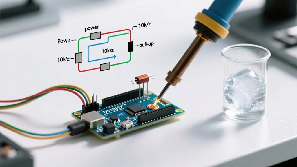
The Arduino I2C specification requires pull-up resistors on SDA and SCL. Most 0.96-inch OLEDs include 4.7kΩ or 10kΩ pull-ups on their breakout boards. However, if you wire multiple sensors and a display to the same I2C bus, the parallel resistance drops. If the total pull-up resistance falls below 2kΩ, the I2C high-state voltage may not reach the 3.3V logic threshold of modern MCUs, resulting in Wire.endTransmission() returning error code 2 (Address NACK). Always measure bus capacitance and stick to 4.7kΩ for 100kHz mode, or 2.2kΩ for 400kHz Fast Mode.
2. Logic Level Shifting for 5V AVRs
Connecting a 3.3V SPI TFT display directly to a 5V Arduino Uno R3 or Mega2560 will eventually destroy the display's shift registers. While cheap resistor-divider circuits work for I2C, they fail catastrophically for high-speed SPI due to capacitance rounding off the square waves. For SPI displays on 5V AVRs, use a dedicated logic level shifter IC like the TXS0108E or discrete BSS138 MOSFET circuits to maintain sharp signal edges at 20MHz+.
3. MISO/MOSI Swap on Custom PCBs
If you are transitioning from a breadboard to a custom PCB using KiCad or Altium, remember that MISO and MOSI labels are relative to the master (Arduino). The MISO pin on your MCU must connect to the MISO pin on the display (which is actually the display's data output). A common PCB layout error is crossing these based on the assumption that 'Output' must connect to 'Input', which will result in a completely blank display despite successful initialization sequences.
Conclusion: Matching the Driver to the Silicon
Selecting the optimal display for Arduino is a dual hardware-software decision. For memory-constrained AVR builds reading basic sensor data, U8g2 in page mode remains unbeatable. For rapid prototyping of color interfaces, Adafruit_GFX provides the lowest barrier to entry. However, for production-grade, high-framerate UIs on 32-bit architectures, mastering TFT_eSPI's DMA configurations and hardware-specific pin mappings is mandatory. By aligning your library choice with your MCU's specific SRAM limits and SPI clock capabilities, you eliminate rendering bottlenecks and ensure robust peripheral operation.