
The Physics of IR Flame Detection
Integrating a flame sensor Arduino setup requires more than just plugging in a module and reading a digital pin. To build reliable safety systems for DIY reflow ovens, automated fireplaces, or robotics, you must understand the underlying physics. Standard infrared (IR) flame sensors detect the specific blackbody radiation emitted by hydrocarbon combustion. While a typical fire emits a broad spectrum of light and heat, the most reliable and consistent emission band for detection lies between 760nm and 1100nm, with a peak sensitivity at 940nm.
Unlike thermistors or thermocouples that measure ambient convective heat (which suffers from severe thermal lag), IR flame sensors detect radiative energy at the speed of light. However, this speed introduces a major integration challenge: the sun, incandescent bulbs, and even warm human skin emit heavily in the 940nm spectrum. Proper hardware selection and software hysteresis are mandatory to prevent false positives.
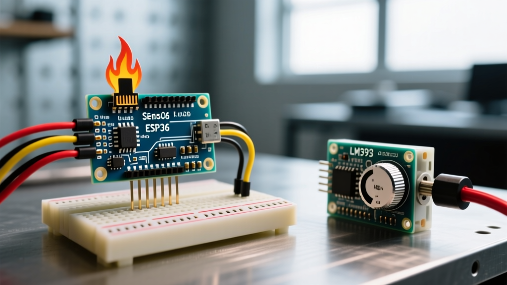
Module Teardown: KY-026 vs. HW-052
As of 2026, the market is dominated by two primary LM393-based modules. Choosing the right one dictates your wiring complexity and noise immunity.
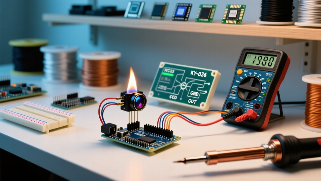
- KY-026 (4-Pin Module): The ubiquitous, budget-friendly option (typically $1.20 to $1.80 per unit). It features a single 940nm photodiode, an LM393 voltage comparator, and a 10kΩ trimpot. It provides both Digital Out (DO) and Analog Out (AO). Its primary flaw is the lack of an enable pin, meaning it draws a constant ~15mA, which is a concern for battery-powered IoT nodes.
- HW-052 (5-Pin Module): A slightly more advanced variant ($2.50 to $3.50). It adds an EN (Enable) pin, allowing the microcontroller to completely power down the sensor's comparator circuit via a MOSFET when not sampling, dropping sleep-state current to microamps. It also typically uses a higher-quality multi-turn trimpot for finer calibration.
For this tutorial, we will focus on the analog integration of the standard 4-pin KY-026, as it represents 90% of hobbyist deployments, but the code architecture applies universally.
Wiring Matrix and Pinout
The LM393 comparator on the module can operate from 3.3V to 5V. If you are using an Arduino Uno R4 Minima or an ESP32, ensure you wire the VCC to the 3.3V pin to prevent overvoltage on the analog input. If using a classic 5V Uno R3, use the 5V rail.
| Sensor Pin | Arduino Uno R3 (5V) | Arduino R4 / ESP32 (3.3V) | Function |
|---|---|---|---|
| VCC | 5V | 3.3V | Powers the LM393 and IR diode |
| GND | GND | GND | Common ground reference |
| DO | Digital Pin 2 | Digital Pin 2 | High/Low based on trimpot threshold |
| AO | Analog Pin A0 | Analog Pin A0 | Raw 0-1023 (or 12-bit) IR intensity |
Note: For robust systems, ignore the DO pin entirely. The hardware comparator on these cheap modules is prone to contact bounce and thermal drift. Reading the AO pin and applying software thresholds yields vastly superior reliability.
The Calibration Protocol (Don't Skip This)
The most common point of failure in a flame sensor Arduino project is improper calibration of the onboard trimpot. Even if you use the Analog pin, the trimpot sets the baseline bias of the photodiode circuit.
- Power the circuit: Upload a blank sketch that simply prints
analogRead(A0)to the Serial Monitor at 115200 baud. - Establish Ambient Baseline: Point the sensor away from any direct light sources. Note the ambient IR reading (usually between 800 and 1023, as higher resistance means less IR detected).
- Introduce a Test Flame: Use a standard butane lighter at exactly 12 inches (30 cm) away. The reading should drop significantly (towards 0).
- Tune the Trimpot: Using a small ceramic flathead screwdriver, adjust the blue trimpot. You want the ambient room reading to sit comfortably around 900-950, and the flame reading to drop below 300. If the ambient reading is pegged at 1023 regardless of adjustment, your IR diode is either reverse-biased (wired backward from the factory) or saturated by a hidden IR source like a TV remote or sunlight.
Robust Arduino C++ Implementation
Beginner tutorials often use delay() and simple if (val < 400) statements. In real-world electrical environments, a flickering flame or passing cloud will cause the sensor value to dance around the threshold, resulting in rapid relay oscillation (chatter) that will destroy mechanical relays and connected peripherals.
The code below implements non-blocking polling via millis() and software hysteresis to ensure clean state transitions.
// Flame Sensor Arduino Integration with Hysteresis
const int FLAME_PIN = A0;
const int RELAY_PIN = 8;

// Thresholds with hysteresis band to prevent relay chatter
const int THRESHOLD_LOW = 400;  // Trigger alarm if IR intensity drops below this
const int THRESHOLD_HIGH = 650; // Clear alarm only if IR intensity rises above this

unsigned long lastReadTime = 0;
const unsigned long READ_INTERVAL = 50; // Poll every 50ms
bool flameDetected = false;

void setup() {
  Serial.begin(115200);
  pinMode(RELAY_PIN, OUTPUT);
  digitalWrite(RELAY_PIN, HIGH); // Assume active-low relay module (safe state)
}

void loop() {
  unsigned long currentMillis = millis();

  if (currentMillis - lastReadTime >= READ_INTERVAL) {
    lastReadTime = currentMillis;

    // Read sensor and apply simple exponential moving average for noise rejection
    int rawValue = analogRead(FLAME_PIN);

    // Hysteresis Logic
    if (!flameDetected && rawValue < THRESHOLD_LOW) {
      flameDetected = true;
      digitalWrite(RELAY_PIN, LOW); // Trigger alarm/extinguisher
      Serial.println("ALARM: Flame Detected!");
    }
    else if (flameDetected && rawValue > THRESHOLD_HIGH) {
      flameDetected = false;
      digitalWrite(RELAY_PIN, HIGH); // Clear alarm
      Serial.println("CLEAR: Flame Extinguished.");
    }

    // Debug output
    Serial.print("Raw IR: ");
    Serial.print(rawValue);
    Serial.print(" | State: ");
    Serial.println(flameDetected ? "DETECTED" : "CLEAR");
  }
}
By maintaining a 250-point gap between THRESHOLD_LOW and THRESHOLD_HIGH, the microcontroller ignores minor IR fluctuations, ensuring the relay only switches when a definitive state change occurs. For deeper insights into analog signal sampling, refer to the official Arduino analogRead() documentation.
Edge Cases and Real-World Failure Modes
When deploying this sensor outside a controlled lab environment, you must engineer around specific physical limitations.
1. The Sunlight Saturation Problem
Direct sunlight contains massive amounts of infrared radiation. If your sensor is placed near a window, the 940nm photodiode will saturate completely, driving the analog reading to near-zero even without a flame. Solution: You must 3D-print or machine a physical shroud (a matte-black tube) that limits the sensor's field of view (FOV) to exactly the target area (e.g., the burner grate). Alternatively, upgrade to a dual-band UV/IR sensor like the Hamamatsu R2868, which ignores solar IR and triggers only on the UV emission of a hydrocarbon flame.
2. The Inverse Square Law and Distance
IR radiation obeys the inverse square law. If you double the distance from the flame to the sensor, the IR intensity drops to one-quarter, not one-half. A sensor calibrated at 6 inches will be completely blind to a 3-inch flame at 24 inches. Always calibrate your trimpot and software thresholds at the maximum expected operational distance.
3. AC Flicker Interference
Incandescent and halogen bulbs emit IR that pulses at the frequency of the AC mains (100Hz or 120Hz depending on your region). If your READ_INTERVAL in the code above happens to alias with this flicker, you will get false readings. The 50ms polling rate (20Hz) generally avoids severe aliasing, but adding a 100nF ceramic capacitor in parallel with the sensor's analog output pin to ground will create a hardware low-pass filter, smoothing out high-frequency AC light noise before it reaches the Arduino's ADC.
Expert Tip: The LM393 comparator chip is highly susceptible to voltage ripple on the VCC line. If you are powering your Arduino and sensor from a cheap switch-mode buck converter, inject a 10µF electrolytic capacitor across the sensor's VCC and GND pins. For comprehensive electrical characteristics of the comparator, consult the Texas Instruments LM393 Datasheet.
Conclusion
Building a reliable flame sensor Arduino system requires moving beyond simple digital reads. By leveraging the analog output, applying software hysteresis, physically shrouding the photodiode, and filtering AC noise, you transform a $1.50 hobbyist component into a robust, industrial-grade safety peripheral. Always test your final deployment with a controlled hydrocarbon source and verify the relay switching behavior under worst-case ambient lighting conditions.