
The Reality of Multi-Peripheral Color Sensor Arduino Setups
Connecting a single sensor to a microcontroller is a weekend warm-up. However, building a robust, multi-peripheral color sensor Arduino system—where a TCS34725 colorimeter shares an I2C bus with an SSD1306 OLED display while simultaneously triggering an MG90S sorting servo—introduces a cascade of hardware and software edge cases. In 2026, while component prices have stabilized and high-quality clones are abundant, the physics of I2C bus capacitance, optical interference, and servo-induced voltage brownouts remain unforgiving.
This guide moves beyond basic blinking LEDs. We will engineer a complete optical sorting node, addressing the specific failure modes that cause 90% of multi-sensor projects to fail in real-world environments. According to the Adafruit Color Sensor Guide, ambient light rejection and consistent illumination are the primary bottlenecks for colorimetric accuracy. When you add a high-torque servo and a display to the mix, power integrity becomes your second major hurdle.
Hardware Selection & Bill of Materials (BOM)
Choosing the right components prevents bus contention and mechanical failure. The TCS3200 is an older frequency-based sensor that requires multiple digital pins and manual LED pulsing. For a multi-peripheral setup, the I2C-based TCS34725 is mandatory to save GPIO pins for other peripherals.
| Component | Model / Spec | Est. Cost (2026) | Role in Setup |
|---|---|---|---|
| Color Sensor | TCS34725 (Genuine ams OSRAM) | $4.50 | RGB + Clear light sensing via I2C |
| Display | SSD1306 128x64 OLED (I2C) | $5.00 | Real-time RGB ratio feedback |
| Actuator | MG90S Metal Gear Servo | $3.50 | Sorting gate mechanism (1.8kg-cm torque) |
| Power Supply | LM2596 5V 2A Buck Converter | $2.00 | Isolated servo power rail |
| Microcontroller | Arduino Nano 33 IoT or Uno R4 | $12.00 - $22.00 | Central logic and I2C master |
I2C Bus Management and Wiring
The Arduino Wire Library handles I2C communication, but it does not protect you from hardware-level capacitance issues. The TCS34725 operates at I2C address 0x29, while the SSD1306 OLED typically sits at 0x3C. Sharing these lines requires strict attention to signal integrity.
Pro-Tip: The 400pF Capacitance Limit
Every wire, breadboard contact, and breakout board adds parasitic capacitance to the I2C bus. The standard I2C specification limits bus capacitance to 400pF. If your OLED and sensor wires exceed 15cm in length, the signal edges will degrade, causing the OLED to freeze or the sensor to return0xFFFFraw values. Use thick, twisted-pair wires for SDA/SCL, or implement an I2C bus extender like the PCA9615 for remote sensor placement.
Wiring Checklist
- SDA / SCL: Connect both the TCS34725 and SSD1306 to the hardware I2C pins (A4/A5 on Uno, or dedicated SDA/SCL pins on Nano 33 IoT).
- Pull-Up Resistors: The Adafruit TCS34725 breakout includes 10kΩ pull-ups. The OLED usually has 4.7kΩ pull-ups. In parallel, this yields roughly 3.2kΩ, which is perfectly safe for 400kHz Fast-mode I2C. Do not add external resistors unless using bare modules.
- Voltage Levels: The TCS34725 is a 3.3V device. If using a 5V Arduino Uno, ensure your breakout board has an onboard LDO and logic-level shifters. The Arduino Nano 33 IoT is natively 3.3V, making it the superior choice for direct I2C interfacing without level-shifting overhead.
Power Delivery: Preventing Servo-Induced Brownouts
The most common point of failure in a multi-peripheral color sensor Arduino project is the power rail. When the MG90S servo actuates to move the sorting gate, it can draw upward of 700mA in a stall condition. If the servo shares the Arduino's onboard 5V linear regulator, this current spike will cause a voltage brownout. The Arduino will reset, the I2C bus will lock up, and the OLED will display garbage data.
The Solution: Use an external LM2596 buck converter set precisely to 5.0V. Power the MG90S servo directly from this buck converter. Crucially, you must tie the ground of the buck converter to the ground of the Arduino. Without a common ground reference, the PWM signal from the Arduino's digital pin 9 will be unreadable by the servo controller.
Optical Isolation: The Hidden Variable
According to the SparkFun TCS34725 Hookup Guide, the sensor features an IR-blocking filter, which is vital for rejecting incandescent and sunlight infrared noise. However, it cannot block visible ambient light flicker from 60Hz LED room lighting. If you rely on room lighting, your Clear (C) channel readings will fluctuate wildly, ruining your color ratios.
Building the Shroud
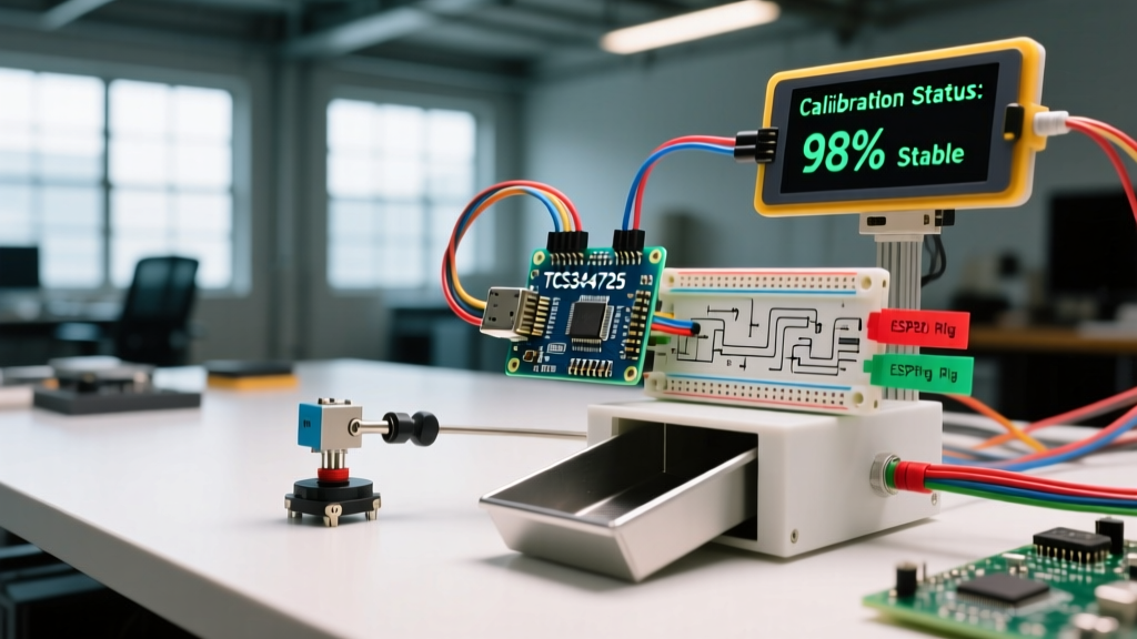
- 3D Print an Enclosure: Design a matte-black shroud that positions the TCS34725 exactly 12mm above the target object. This is the optimal focal distance for the sensor's photodiode array.
- Integrated Illumination: The Adafruit breakout includes a onboard white LED. Solder a jumper to the LED pin so you can toggle it via GPIO. Turn the LED on 50ms before taking a reading, and turn it off immediately after to prevent thermal drift in the sensor's silicon.
- Target Background: Place a neutral gray (18% reflectance) cardstock at the bottom of the sorting chute. This provides a consistent baseline when the sensor is reading 'empty' state.
Calibration Logic: Raw Data vs. Relative Ratios
Never use raw 16-bit RGB values for sorting logic. Raw values are entirely dependent on the distance to the object and the exact voltage of your white LED. Instead, you must normalize the data into relative percentages using the Clear (C) channel as your luminosity baseline.
Use the following mathematical approach in your C++ sketch:
// Read raw 16-bit data
uint16_t r, g, b, c;
colorSensor.getRawData(&r, &g, &b, &c);

// Prevent division by zero
if (c == 0) c = 1;

// Calculate relative ratios (0.0 to 1.0)
float r_ratio = (float)r / (float)c;
float g_ratio = (float)g / (float)c;
float b_ratio = (float)b / (float)c;

// Scale to 255 for standard RGB representation
int final_r = r_ratio * 255;
int final_g = g_ratio * 255;
int final_b = b_ratio * 255;
By sorting based on r_ratio, g_ratio, and b_ratio, your Arduino will correctly identify a red object whether it is a dark red wooden block or a bright red plastic bottle, because the proportion of red light reflected remains constant relative to the total light absorbed.
Troubleshooting Edge Cases
- Sensor returns ID 0x00 or 0xFF on I2C Scan
- This indicates the Arduino cannot see the TCS34725. Check your SDA/SCL wiring. If using a clone board, verify the onboard 3.3V LDO hasn't failed. Clone boards from early 2024 batches frequently suffered from cold solder joints on the I2C pull-up resistor array.
- OLED Display Freezes After Servo Movement
- This is an EMI (Electromagnetic Interference) issue. The MG90S servo motor generates significant electrical noise on the power rail when braking. Add a 100µF electrolytic capacitor and a 0.1µF ceramic capacitor in parallel across the servo's power terminals to suppress high-frequency noise from reaching the I2C pull-ups.
- Inconsistent Readings on Shiny Objects
- Specular reflection (glare) blinds the photodiodes. If sorting metallic or glossy items, angle the TCS34725 shroud at a 15-degree offset rather than pointing it straight down. This allows the sensor to read the diffuse color scatter rather than the direct reflection of the onboard white LED.
- Integration Time Errors
- The TCS34725 allows custom integration times. For a fast-moving conveyor belt, set the integration time to 2.4ms (register
0xFF). For high-precision sorting of similar pastel shades, increase it to 614ms (register0x00) to maximize the signal-to-noise ratio, though this limits your sorting speed to roughly 1 object per second.
Final System Integration
By treating your color sensor Arduino setup not as a collection of isolated parts, but as an integrated electro-optical system, you eliminate the guesswork. Managing the 400pF I2C capacitance limit, isolating the servo power rail, and normalizing RGB data against the Clear channel transforms a fragile prototype into an industrial-grade sorting peripheral ready for continuous 24/7 operation.