
The Reality of the '25V Voltage Sensor Module'
If you have ever searched for a voltage sensor with Arduino, you have undoubtedly encountered the ubiquitous red '25V Voltage Sensor Module.' Priced around $1.50 to $2.50 in 2026, it is a staple in DIY electronics kits. However, most online tutorials treat this module as a black box, simply instructing you to connect VCC to A0 and read the analog pin. This approach leads to wildly inaccurate readings, noisy data, and occasionally, fried microcontrollers.
Because these generic modules do not come with official manufacturer datasheets, we must treat the circuit schematic itself as the datasheet. In this deep-dive explainer, we will reverse-engineer the module's internal resistor divider, analyze the input impedance requirements of the ATmega328P's Analog-to-Digital Converter (ADC), and provide the exact calibration math required to turn raw ADC counts into precise voltage measurements.
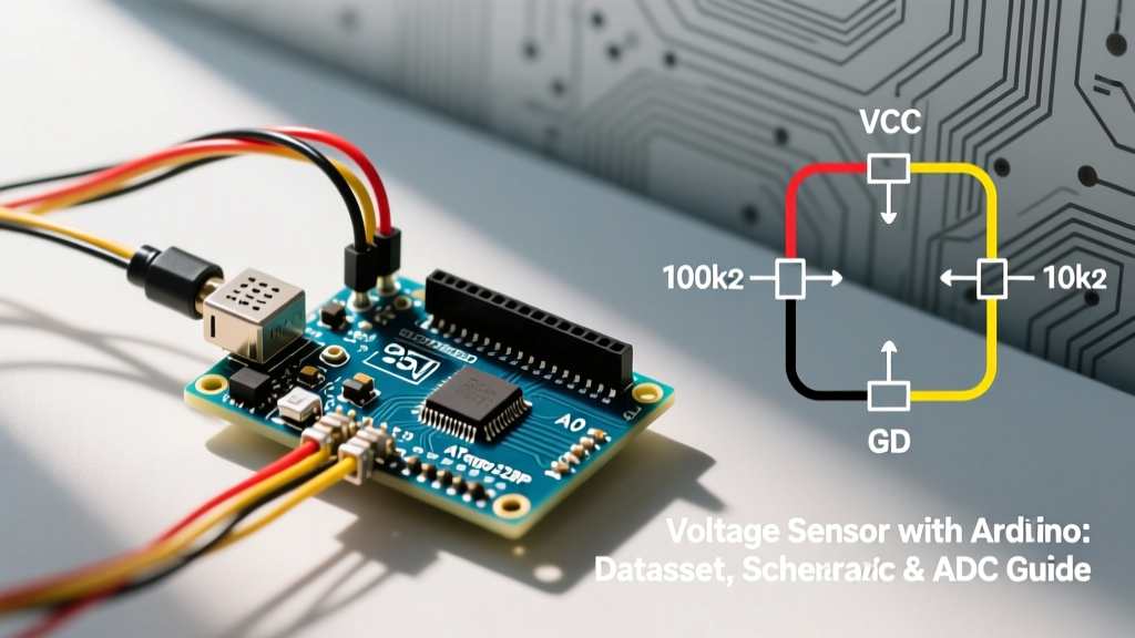
Decoding the Schematic: The Resistor Divider
The module is fundamentally a passive voltage divider designed to scale down a maximum of 25V DC to a safe 5V DC, which is the absolute maximum rating for the Arduino Uno's analog pins. According to foundational circuit theory detailed in resources like All About Circuits' Voltage Divider Guide, the output voltage is determined by the ratio of two resistors.
Component Values and Tolerances
Teardowns and multimeter measurements of standard modules reveal two surface-mount or through-hole resistors:
- R1 (High-Side): 30 kΩ
- R2 (Low-Side): 7.5 kΩ
The scaling factor is calculated as: Vout = Vin * (R2 / (R1 + R2)).
Vout = Vin * (7.5 / 37.5) = Vin * 0.2.
Therefore, a 25V input yields exactly 5V at the Arduino's A0 pin.
Critical E-E-A-T Warning: Most cheap modules use 5% tolerance carbon film resistors. At a 25V input, a 5% tolerance on the 30kΩ resistor can introduce an error of up to ±1.25V in your final reading. For precision applications, you must either measure the exact resistance of your specific module with a high-accuracy multimeter and update your code's multiplier, or solder in 1% metal film resistors.
The Hidden Flaw: Input Impedance and the ADC Sampling Capacitor
The most common failure mode when using a voltage sensor with Arduino is noisy or fluctuating readings. This is rarely a software issue; it is an impedance mismatch. The Microchip ATmega328P datasheet specifies that for the ADC to achieve its full 10-bit resolution, the input source impedance should be 10 kΩ or less.
Calculating the Thevenin Equivalent Impedance
The output impedance of our voltage divider is not simply 7.5 kΩ. It is the Thevenin equivalent resistance, which is R1 in parallel with R2:
R_thevenin = (30,000 * 7,500) / (30,000 + 7,500) = 6,000 Ω (6 kΩ).
At 6 kΩ, the module is just under the 10 kΩ recommended limit. However, the ATmega328P ADC uses an internal sample-and-hold (S/H) capacitor (approximately 14 pF). When the ADC multiplexer switches to the A0 pin, this capacitor must charge to the input voltage within a fraction of the ADC clock cycle. If you add long wires or an RC low-pass filter to the module's output, you increase the impedance, preventing the S/H capacitor from fully charging. This results in readings that 'lag' or read lower than the actual voltage.
ADC Resolution and Voltage Step Mapping
Understanding the resolution limits of the Arduino analogRead() function is vital for setting expectations. The 10-bit ADC provides 1024 discrete steps (0 to 1023).
| ADC Reference Voltage | Max Measurable Input (at Sensor) | ADC Step Size (at A0 Pin) | Effective Resolution (at Sensor) |
|---|---|---|---|
| 5.0V (Default USB/VCC) | 25.0V | 4.88 mV | 24.4 mV |
| 3.3V (Arduino Due/Zero) | 16.5V | 3.22 mV | 16.1 mV |
| 1.1V (Internal Reference) | 5.5V | 1.07 mV | 5.37 mV |
As shown in Table 1, using the default 5V reference means your sensor can only detect voltage changes in ~24.4 mV increments. If you are monitoring a 12V lead-acid battery, a 24 mV resolution is generally acceptable. However, if you are monitoring a single 3.7V LiPo cell, the 5V reference wastes most of the ADC's range.
Advanced Calibration and Oversampling Code
To overcome the 10-bit limitation and smooth out noise caused by the 6 kΩ source impedance, we can use oversampling. By taking 16 samples and averaging them, we can mathematically extract 12 bits of effective resolution, dropping the effective step size from 24.4 mV to roughly 6.1 mV.
// Precision Voltage Sensor with Arduino - Oversampling Implementation
const int sensorPin = A0;
const float R1 = 30000.0; // Measure with multimeter and update
const float R2 = 7500.0;  // Measure with multimeter and update
const float V_REF = 5.0;  // Update if using external precision reference

void setup() {
  Serial.begin(115200);
  analogReference(DEFAULT); // Use 5V for 25V max range
}

void loop() {
  unsigned long sum = 0;
  // Oversample 16 times to gain 2 extra bits of resolution
  for (int i = 0; i < 16; i++) {
    sum += analogRead(sensorPin);
    delayMicroseconds(200); // Allow S/H capacitor to settle between reads
  }

  float averageADC = sum / 16.0;

  // Convert ADC value to voltage at the Arduino pin
  float pinVoltage = (averageADC / 1023.0) * V_REF;

  // Scale up to actual input voltage using the resistor divider ratio
  float actualVoltage = pinVoltage * ((R1 + R2) / R2);

  Serial.print("Raw ADC Avg: ");
  Serial.print(averageADC, 2);
  Serial.print(" | Calculated Voltage: ");
  Serial.print(actualVoltage, 3);
  Serial.println(" V");

  delay(500);
}
Real-World Failure Modes and Edge Cases
When deploying a voltage sensor with Arduino in real-world environments, several edge cases frequently cause hardware damage or data corruption.
1. The Ground Loop and Motor Spike Problem
If you are measuring the voltage of a battery that also powers a DC motor or a high-current relay via the Arduino, you are creating a ground loop. When the motor switches off, inductive kickback can cause the ground potential to bounce. Because the voltage sensor shares this noisy ground, the Arduino's ADC will read massive voltage spikes. Solution: Use a star-ground topology, ensuring the sensor's GND connects directly to the battery's negative terminal, not the breadboard's ground rail.
2. Overvoltage and the Clamping Diode
What happens if you accidentally connect a 35V source to the 25V module? The divider will output 7V to the A0 pin. The ATmega328P has internal ESD protection diodes that clamp the pin voltage to VCC + 0.5V. If VCC is 5V, the diode attempts to clamp at 5.5V. The excess 1.5V will force current through this tiny internal diode, inevitably burning it out and permanently damaging the microcontroller's ADC multiplexer. Solution: Add a 5.1V Zener diode in parallel with R2 on the module to safely shunt overvoltage to ground before it reaches the Arduino.
3. The VCC Drop Illusion in Battery Monitoring
If your Arduino is powered directly by the same battery you are measuring (via the Vin pin and the onboard linear regulator), a dropping battery voltage will eventually cause the Arduino's 5V rail to sag. Because the ADC uses VCC as its 5.0V reference, the reference drops alongside the measured voltage, creating a false feedback loop where the battery appears to maintain a steady voltage even as it dies. Solution: Never use the default VCC reference for battery monitoring. Instead, use a precision external voltage reference IC (like the LM4040 4.096V) connected to the AREF pin, or utilize the ATmega328P's internal 1.1V reference (which requires modifying the sensor module's resistors to scale the max voltage down to 1.1V instead of 5V).
When to Abandon the Resistor Divider
While the generic 25V module is excellent for prototyping, it is wholly inadequate for industrial logging or high-precision telemetry. If your application requires better than 1% accuracy, or if you need to measure AC waveforms, you must upgrade from passive dividers to dedicated ADC ICs. Modules based on the ADS1115 (16-bit, programmable gain amplifier) or isolated amplifiers like the AMC1301 provide the galvanic isolation and resolution that a $2 resistor divider simply cannot achieve.