
Why Direct Arduino PWM Fails for Multi-Servo Setups
When building a complex robotic arm, hexapod, or animatronic rig, relying on the standard Arduino Servo.h library quickly becomes a bottleneck. The ATmega328P and ESP32 microcontrollers generate PWM signals using internal hardware timers. Once you exceed 12 servos on an Uno, or attempt to mix servos with DC motors, timer conflicts cause severe signal jitter, resulting in erratic servo twitching and potential gear stripping.
The industry-standard solution is to offload PWM generation to a dedicated Arduino servo controller IC. The NXP PCA9685 16-channel I2C PWM driver handles all pulse-width modulation internally via a 25MHz clock, communicating with your microcontroller solely over the I2C bus. This frees up your MCU for kinematic calculations while delivering rock-solid, jitter-free signals to up to 16 servos per board (and up to 62 servos via daisy-chaining).
Hardware BOM and Power Sizing
A common failure mode in DIY robotics is under-sizing the power supply. Standard USB power (500mA) or linear regulators (like the L7805) will instantly brownout when multiple high-torque servos stall simultaneously. Below is a recommended Bill of Materials for a robust 6-servo robotic arm setup.
| Component | Model / Specification | Est. Price (2026) | Notes |
|---|---|---|---|
| PWM Driver | Adafruit PCA9685 Breakout (or generic clone) | $14.95 / $4.50 | Genuine includes premium headers & reverse-polarity protection. |
| Servos (x6) | TowerPro MG996R (Metal Gear) | $6.00 each | Stall current: 2.5A at 6V. Total peak draw: 15A. |
| Power Supply | Mean Well LRS-100-5 (5V 18A) | $22.00 | Enclosed switching PSU. Handles 15A peak with headroom. |
| Wiring | 18 AWG Silicone Wire (Power), 26 AWG (I2C) | $12.00 | Thin I2C wires increase bus capacitance; keep under 30cm. |
Critical Wiring: The VCC vs. V+ Distinction
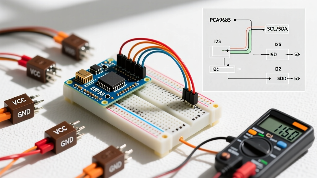
The most frequent mistake when wiring a PCA9685 breakout board is confusing the logic power (VCC) with the servo power (V+). Failing to separate these will either fry your microcontroller's I2C pins or cause the PCA9685 to reset under load.
⚠️ Wiring Rule of Thumb:
VCC (Logic): Connect to your Arduino's 5V or 3.3V pin. This powers the internal I2C logic of the PCA9685 chip.
V+ (Servo Power): Connect directly to the positive terminal of your dedicated 5V/6V servo power supply. Do NOT route this through the Arduino's 5V pin.
Step-by-Step I2C Connections
- GND: Connect the PCA9685 GND to both the Arduino GND and the Servo Power Supply GND. A common ground is mandatory for I2C reference.
- SDA/SCL: Connect to the Arduino's dedicated I2C pins (A4/A5 on Uno, D20/D21 on Mega, or specific SDA/SCL pins on ESP32).
- OE (Output Enable): Tie this pin to GND to permanently enable the outputs. If you need to kill power to all servos via code, connect OE to a digital pin and pull it HIGH to disable.
I2C Address Configuration
Out of the box, the PCA9685 responds to the I2C address 0x40. If your project requires more than 16 servos, you can daisy-chain up to 62 boards by soldering the A0 through A5 jumpers on the right side of the PCB. Each closed jumper shifts the address. For example, closing the A0 jumper changes the address to 0x41. Refer to the NXP PCA9685 Datasheet for the complete 7-bit address mapping table.
The Math: Calculating 12-Bit PWM Tick Values
Unlike the Arduino analogWrite() function which uses 8-bit resolution (0-255), the PCA9685 uses a 12-bit timer, yielding 4096 discrete steps (0-4095) per cycle. To write precise code, you must translate standard servo pulse widths (typically 1ms to 2ms) into these 12-bit ticks.
Standard hobby servos expect a 50Hz signal, meaning one full cycle takes 20ms (1000ms / 50Hz).
- Resolution: 4096 ticks / 20ms = 204.8 ticks per millisecond.
- Minimum Pulse (approx 0°): 1ms × 204.8 = ~205 ticks (often calibrated down to 150 for full range).
- Maximum Pulse (approx 180°): 2ms × 204.8 = ~410 ticks (often calibrated up to 600).
By calculating these tick values manually rather than relying on wrapper libraries that guess your servo's physical limits, you eliminate the "hunting" behavior where a servo vibrates at the end of its travel.
Jitter-Free C++ Implementation
Below is a production-ready implementation using the Arduino Wire Library and the Adafruit PWM framework. This code includes an I2C bus initialization check and a smooth sweep function.
#include <Wire.h>
#include <Adafruit_PWMServoDriver.h>

// Initialize the PCA9685 at default I2C address 0x40
Adafruit_PWMServoDriver pwm = Adafruit_PWMServoDriver(0x40);

// Servo calibration limits (in 12-bit ticks)
#define SERVO_MIN  150  // ~0.75ms pulse
#define SERVO_MAX  600  // ~2.9ms pulse
#define SERVO_FREQ 50   // Standard analog servos run at ~50 Hz

void setup() {
  Serial.begin(115200);

  // Initialize I2C and verify connection
  Wire.begin();
  pwm.begin();
  pwm.setOscillatorFrequency(27000000); // Internal 25MHz clock tuning
  pwm.setPWMFreq(SERVO_FREQ);

  // Allow time for the first I2C transaction to settle
  delay(10);
  Serial.println("PCA9685 Arduino Servo Controller Initialized.");
}

void loop() {
  // Sweep Servo on Channel 0 from Min to Max
  for (uint16_t pulselen = SERVO_MIN; pulselen < SERVO_MAX; pulselen++) {
    pwm.setPWM(0, 0, pulselen);
    delay(5); // 5ms delay creates a smooth, slow sweep
  }

  delay(500);

  // Sweep back
  for (uint16_t pulselen = SERVO_MAX; pulselen > SERVO_MIN; pulselen--) {
    pwm.setPWM(0, 0, pulselen);
    delay(5);
  }

  delay(500);
}
Advanced Troubleshooting & Edge Cases
Even with perfect code, physical layer issues can plague an Arduino servo controller setup. Here is how to diagnose the three most common field failures:
1. Random Servo Twitching (I2C Bus Capacitance)
The I2C protocol relies on open-drain lines pulled high by resistors. The PCA9685 breakout includes 10kΩ pull-up resistors. If you use long wires (over 30cm) or daisy-chain multiple boards, the parasitic capacitance of the wires slows down the signal rise time, causing the Arduino to misread ACK/NACK bits. Fix: Solder additional 4.7kΩ or 2.2kΩ pull-up resistors directly to the SDA and SCL headers on the master board to stiffen the bus.
2. Microcontroller Brownouts (Ground Bounce)
When six MG996R servos change direction simultaneously, they can pull 15A in a fraction of a second. If your ground wiring is daisy-chained using thin breadboard jumper wires, the voltage drop across the ground wire creates a "ground bounce." The Arduino's ground reference spikes above the PCA9685's ground, corrupting I2C data. Fix: Use a star-ground topology. Run thick 18 AWG ground wires from the power supply directly to a central terminal block, and branch out to the Arduino and PCA9685 V+ terminals individually.
3. Servo "Hunting" at Neutral Position
If your servo continuously vibrates when commanded to hold a static position, your pulse width is likely slightly outside the servo's internal potentiometer deadband. Fix: Implement a software deadband in your kinematics code. If the calculated tick difference between the current position and target position is less than 3 ticks (~0.015ms), do not send a new I2C command. This reduces I2C bus traffic and stops the physical hunting.
For further reading on advanced I2C topologies and multi-master configurations, consult the Adafruit 16-Channel PWM Servo Driver Guide, which provides excellent oscilloscope captures of signal degradation over varying wire lengths.