
Mastering Sensor Integration: Beyond the Basic Tutorial
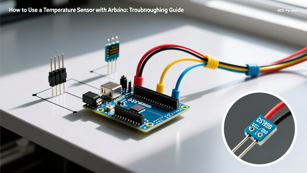
Learning how to use a temperature sensor with Arduino is a foundational rite of passage for every electronics enthusiast. You wire up a DS18B20 or an LM35, copy a library example, and expect perfect serial monitor output. But real-world physics rarely cooperates. Instead of a clean 22.5°C, you are greeted with wild fluctuations, a stubborn -127°C error, or a complete I2C bus lockup that freezes your microcontroller.
In 2026, with the widespread adoption of the Arduino UNO R4 Minima and Wi-Fi-enabled ESP32-S3 boards, sensor integration is more powerful but also more sensitive to timing and impedance mismatches. This guide bypasses the basic wiring diagrams and dives straight into advanced troubleshooting, addressing the specific failure modes, edge cases, and hardware quirks that plague temperature sensing projects.
Temperature Sensor Landscape: Quick Reference Matrix
Before troubleshooting, confirm you are applying the correct electrical rules for your specific sensor architecture. Mixing up protocols is the leading cause of hardware damage and silent data corruption.
| Sensor Model | Protocol | Typical Accuracy | 2026 Avg. Price | Primary Failure Mode |
|---|---|---|---|---|
| DS18B20 (Genuine) | 1-Wire | ±0.5°C | $4.50 | Parasitic power sag, missing pull-up |
| LM35Z | Analog (10mV/°C) | ±0.25°C | $2.10 | ADC noise, floating ground |
| TMP117 | I2C | ±0.1°C | $3.80 | Bus lockup, missing SDA/SCL pull-ups |
Troubleshooting 1-Wire Sensors (DS18B20)
The Maxim Integrated (now Analog Devices) DS18B20 is the most popular digital temperature sensor, but its 1-Wire protocol is notoriously unforgiving regarding timing and bus capacitance.
Symptom: The Sensor Reads Exactly 85.0°C
If your serial monitor outputs a flat 85.0°C on the first read, or intermittently, you are reading the sensor's Power-On Reset (POR) scratchpad value. The sensor has not actually performed a temperature conversion.
- The Cause: The master (Arduino) issued the
convertTcommand but attempted to read the scratchpad before the conversion finished. At 12-bit resolution, the DS18B20 requires up to 750ms to complete the ADC conversion. - The Fix: Ensure your code includes a
delay(750)after requesting conversion, or use the library'sisConversionComplete()polling method. If you are using parasite power mode (powering the sensor via the data line), the VDD pin must be tied to GND, and the master must provide a strong pull-up (via a MOSFET) during conversion to supply the required 1.5mA of current.
Symptom: The Sensor Reads -127.0°C or Disconnects
A reading of -127.0°C is the DallasTemperature library's default error code for a CRC mismatch or a completely absent device on the bus.
- The Cause: Missing or incorrect pull-up resistor on the data line, or excessive cable capacitance destroying the sharp 1-Wire timing edges.
- The Fix: Verify a 4.7kΩ resistor is connected between the DATA line and VCC (3.3V or 5V). If your cable exceeds 3 meters, the parasitic capacitance will round off the microsecond pulses. Switch to an active 1-Wire master chip like the DS2482-100, or lower the pull-up resistor to 2.2kΩ to speed up the RC rise time.
Expert Tip: Beware of counterfeit DS18B20 sensors flooding the market at $1.00 each. Clones often fail the CRC check at higher resolutions or drop off the bus when multiple sensors are chained. Always source genuine Analog Devices chips from authorized distributors like Mouser or DigiKey for mission-critical builds.
Troubleshooting Analog Sensors (LM35 / TMP36)
Analog sensors output a continuous voltage proportional to temperature. While they require no complex libraries, they are highly susceptible to electromagnetic interference (EMI) and ADC quantization errors.
Symptom: Wildly Fluctuating Readings (e.g., 21°C to 28°C in milliseconds)
The LM35 outputs 10mV per degree Celsius. At room temperature (22°C), the output is a mere 220mV. Any noise on the line is amplified by your code.
- The Cause: The Arduino's ADC sample-and-hold capacitor requires a low-impedance source to charge accurately. Long, unshielded wires act as antennas, picking up 50/60Hz mains hum and RF interference from nearby Wi-Fi routers.
- The Fix (Hardware): Solder a 100nF (0.1µF) ceramic decoupling capacitor directly between the sensor's VOUT and GND pins. Use twisted-pair wire for the signal and ground lines to cancel out common-mode magnetic interference.
- The Fix (Software): Implement oversampling. Read the analog pin 16 times, sum the values, and divide by 16. This mathematically filters out high-frequency white noise and effectively increases your ADC resolution by 2 bits.
Symptom: Poor Resolution (Readings Jump in 0.5°C Increments)
Using the default 5V reference on an Arduino UNO R3 yields an ADC resolution of 4.88mV per step (5V / 1024). Since the LM35 outputs 10mV/°C, your temperature resolution is limited to roughly 0.5°C.
- The Fix: Switch the ADC reference voltage. On the classic UNO R3, use
analogReference(INTERNAL)to switch to the 1.1V internal reference, boosting resolution to ~0.1°C per step. If you are using the modern Arduino UNO R4 Minima, the ADC is 14-bit and operates differently; utilize the 2.5V internal reference viaanalogReference(AR_INTERNAL2V5)to maximize the dynamic range for the 0-100°C sensing window.
Troubleshooting I2C Temperature Sensors (TMP117 / BME280)
High-accuracy I2C sensors like the Texas Instruments TMP117 offer 16-bit resolution but rely on the I2C bus, which is notoriously fragile in DIY wiring setups.
Symptom: Complete Bus Lockup (SDA Stuck LOW)
Your Arduino freezes, or Wire.available() perpetually returns 0. The I2C bus is a wired-AND configuration; if any device pulls the SDA line LOW, the entire bus halts.
- The Cause: If the Arduino resets or loses power mid-transaction while the sensor is outputting a '0' bit, the sensor will hold SDA low, waiting for the master to provide the 9th clock pulse (ACK). Upon rebooting, the master sees a busy bus and hangs.
- The Fix: Implement an I2C bus recovery sequence in your
setup()function. Before callingWire.begin(), configure the SCL pin as a standard GPIO output and toggle it HIGH and LOW 9 times. This forces the stuck sensor to clock out its remaining bits and release the SDA line.
Symptom: Intermittent Data Corruption or NACK Errors
- The Cause: Missing pull-up resistors. Many cheap breakout boards omit I2C pull-ups, assuming the Arduino's internal pull-ups (approx. 30kΩ - 50kΩ) are sufficient. They are not. The I2C specification requires a rise time of less than 300ns for standard mode, which 40kΩ internal resistors cannot achieve on a bus with >100pF capacitance.
- The Fix: Always install external 4.7kΩ pull-up resistors on both the SDA and SCL lines to VCC. If you are running the bus at 3.3V (e.g., with an ESP32), use 3.3kΩ resistors to ensure adequate current sinking.
Diagnostic Tools for the Workbench
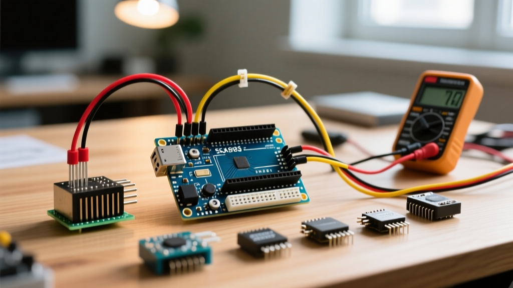
When code and multimeter checks fail, you must visualize the invisible. Keep these tools on your 2026 workbench:
- Logic Analyzer ($15 - $50): Essential for decoding 1-Wire timing. A standard 24MHz 8-channel USB logic analyzer running Sigrok/PulseView will instantly reveal if your Arduino's 1-Wire reset pulse is stretching beyond the required 480µs, or if the sensor's presence pulse is missing.
- Oscilloscope (Entry-level $150+): Use this to check for ground bounce on analog sensors. Probe the sensor's GND pin relative to the Arduino's GND pin; if you see millivolt-level AC noise, you have a ground loop or inadequate power supply decoupling.
- I2C Scanner Sketch: Never attempt to debug a complex sensor library without first running a raw I2C scanner. If the sensor's hex address (e.g., 0x48 for TMP117) does not appear in the serial output, no amount of library tweaking will fix a hardware wiring fault.
Summary
Understanding how to use a temperature sensor with Arduino goes far beyond copying a schematic. It requires a deep appreciation for bus capacitance, ADC reference voltages, and protocol timing. By methodically isolating hardware faults—such as missing pull-ups, parasitic power sags, and ground loops—from software errors, you can transform erratic, noisy data into rock-solid, laboratory-grade measurements.