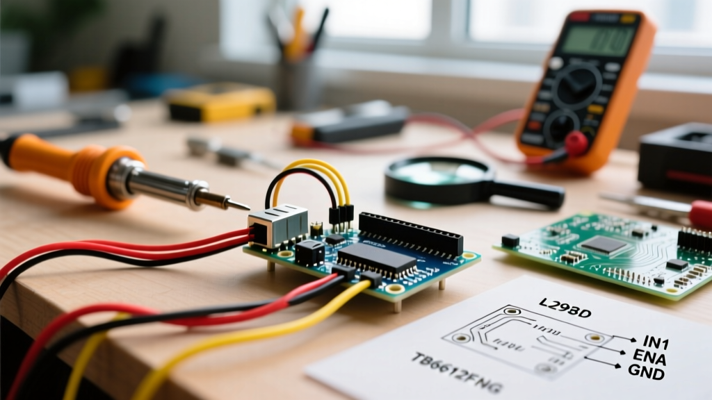

Why Microcontrollers Cannot Drive Motors Directly
A common mistake among beginners in robotics and mechatronics is attempting to wire a DC motor directly to the digital pins of a microcontroller. While an Arduino Uno (based on the ATmega328P) outputs 5V logic, its GPIO pins are strictly limited to a maximum current of 40mA per pin (with a recommended safe operating limit of 20mA). A standard 130-size hobby DC motor typically draws between 150mA and 300mA under normal load, and can spike to over 1A during stall conditions.
Connecting a motor directly to an Arduino pin will instantly fry the microcontroller's internal silicon. Furthermore, motors are inductive loads. When power is cut, the collapsing magnetic field generates a reverse voltage spike known as back-EMF, which can destroy sensitive logic circuits. This is exactly why you must use a motor driver module as an intermediary power stage.
Choosing Your Hardware: L298N vs. TB6612FNG
When searching for a motor driver module for Arduino projects, two ICs dominate the hobbyist market in 2026: the classic STMicroelectronics L298N and the modern Toshiba TB6612FNG. Understanding the architectural differences between these two will save you hours of troubleshooting.
| Feature | L298N Module (Red Board) | TB6612FNG Module |
|---|---|---|
| Transistor Type | BJT (Bipolar Junction Transistor) | MOSFET (Metal-Oxide-Semiconductor) |
| Voltage Drop | 1.5V to 2.0V (High heat dissipation) | ~0.5V (Highly efficient) |
| Max Continuous Current | 2A per channel | 1.2A per channel (3.2A peak) |
| PWM Switching Speed | Up to 25 kHz | Up to 100 kHz |
| Typical 2026 Price | $3.50 - $5.00 (Clone boards) | $6.00 - $9.00 (Breakout boards) |
| Best Use Case | Wired desktop robots, high-voltage (12V) setups | Battery-powered rovers, space-constrained builds |
As noted in the Texas Instruments Motor Drivers Overview, modern MOSFET-based H-bridges like the TB6612FNG are vastly superior for battery-operated devices because they waste significantly less energy as heat. However, the L298N remains the undisputed king of beginner tutorials due to its ruggedness, screw-terminal wiring, and extremely low cost.
Step-by-Step: Wiring the L298N to Arduino
For this tutorial, we will focus on the ubiquitous red L298N dual H-bridge module. It features an onboard 5V voltage regulator, opto-isolation jumpers, and heavy-duty heat sinks.
1. Power Supply Connections
- 12V / VCC Terminal: Connect the positive terminal of your external battery pack (e.g., a 2S LiPo at 7.4V or a 4x AA holder at 6V). Do not exceed 35V absolute maximum.
- GND Terminal: Connect the negative terminal of your battery pack. CRITICAL: You must also run a jumper wire from this GND terminal to any GND pin on your Arduino Uno. Without a common ground, the logic signals will float, and the motor will behave erratically.
- 5V Terminal: If your input voltage is between 7V and 12V, leave the 5V-EN jumper cap ON. The module will output a regulated 5V that you can use to power the Arduino via its 5V pin. If your input voltage exceeds 12V, remove the jumper to prevent frying the onboard linear regulator.
2. Logic and PWM Pin Mapping
The L298N requires six digital pins from the Arduino to control two DC motors independently. Two of these pins must support hardware PWM (indicated by the ~ symbol on the Arduino board) to control motor speed.
| L298N Pin | Arduino Uno Pin | Function |
|---|---|---|
| ENA | Pin 5 (~) | PWM Speed Control for Motor A |
| IN1 | Pin 7 | Direction Logic 1 for Motor A |
| IN2 | Pin 8 | Direction Logic 2 for Motor A |
| IN3 | Pin 9 | Direction Logic 1 for Motor B |
| IN4 | Pin 10 | Direction Logic 2 for Motor B |
| ENB | Pin 6 (~) | PWM Speed Control for Motor B |
Arduino Code: Direction and Speed Control
The following C++ sketch demonstrates how to ramp up the speed of Motor A using the Arduino analogWrite() function, hold it, reverse direction, and brake.
// Motor A Pin Definitions
const int ENA = 5;
const int IN1 = 7;
const int IN2 = 8;

void setup() {
  pinMode(ENA, OUTPUT);
  pinMode(IN1, OUTPUT);
  pinMode(IN2, OUTPUT);

  // Ensure motor is stopped on boot
  digitalWrite(IN1, LOW);
  digitalWrite(IN2, LOW);
}

void loop() {
  // Move Forward, ramping speed from 0 to 255
  digitalWrite(IN1, HIGH);
  digitalWrite(IN2, LOW);
  for (int speed = 0; speed <= 255; speed += 5) {
    analogWrite(ENA, speed);
    delay(50);
  }

  delay(2000); // Hold max speed for 2 seconds

  // Hard Brake
  digitalWrite(IN1, LOW);
  digitalWrite(IN2, LOW);
  analogWrite(ENA, 0);
  delay(1000);

  // Move Backward at fixed 70% speed
  digitalWrite(IN1, LOW);
  digitalWrite(IN2, HIGH);
  analogWrite(ENA, 180);
  delay(3000);

  // Stop
  digitalWrite(IN1, LOW);
  digitalWrite(IN2, LOW);
  delay(2000);
}
Real-World Troubleshooting & Edge Cases
Even with perfect wiring, beginners frequently encounter hardware-level anomalies when interfacing a motor driver module with Arduino. Here is how to diagnose and fix the most common failure modes.
Expert Insight: Never rely on the Arduino's USB 5V power to drive the logic of a motor driver while simultaneously powering high-draw motors from a separate unregulated supply without a common ground. Ground loops and floating references account for 80% of 'erratic motor behavior' forum posts.
Symptom: Arduino Resets When Motor Engages
- The Cause: Voltage sag on the main power rail or back-EMF spikes injecting noise into the Arduino's reset line. When a motor starts, it draws stall current, temporarily dropping the battery voltage below the Arduino's brown-out detection threshold (typically ~2.7V for the ATmega328P).
- The Fix: Solder a 100µF electrolytic capacitor directly across the motor's physical terminals to absorb high-frequency noise. Additionally, add a 470µF decoupling capacitor across the main power supply rails near the L298N's VCC and GND screw terminals to act as a local energy reservoir during stall-current spikes.
Symptom: Motor Hums but Does Not Spin at Low PWM
- The Cause: DC motors require a minimum threshold of torque to overcome static mechanical friction and cogging. An
analogWrite()value of 30 or 40 might supply enough voltage to energize the coils (causing a hum) but not enough current to initiate rotation. - The Fix: Implement a 'kickstart' routine in your code. Send a brief pulse of
analogWrite(ENA, 255)for 50 milliseconds to break static friction, immediately followed by your desired lower PWM cruising speed (e.g.,analogWrite(ENA, 90)).
When to Upgrade to the TB6612FNG
If your project transitions from a tethered desktop prototype to an autonomous, battery-powered rover, the L298N's 2V voltage drop becomes a massive liability. For example, if you supply 6V from a 4xAA battery pack, the L298N will deliver only 4V to your motors, severely reducing torque and battery life. According to the SparkFun TB6612FNG Hookup Guide, upgrading to a MOSFET-based driver ensures that a 6V input yields roughly 5.5V at the motor terminals. This 25% increase in delivered power translates to noticeably faster acceleration, better obstacle climbing, and up to 40% longer runtime on the same battery chemistry.
Summary Checklist for Success
- Verify your external power supply can deliver at least 1.5A continuous current.
- Always connect the Arduino GND to the Motor Driver GND.
- Ensure ENA and ENB are connected to PWM-capable pins (~).
- Add physical decoupling capacitors to the motor terminals to protect your logic ICs.