
The Reality of Seven Segment Arduino Integrations
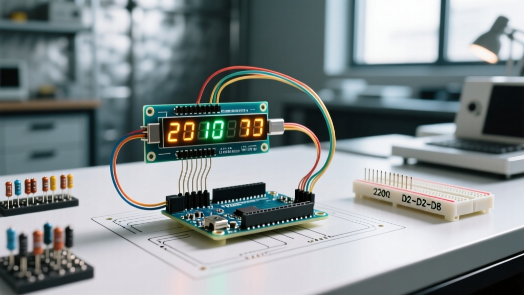
Integrating a seven segment Arduino display into your project seems straightforward until you power it on and face flickering digits, dim segments, or ghosting cross-talk. While modern OLEDs and TFTs dominate 2026 hobbyist projects, 7-segment displays remain the gold standard for high-visibility, rugged industrial interfaces, retro clocks, and high-brightness dashboards. However, driving them directly from an ATmega328P or ESP32 without proper hardware multiplexing or dedicated driver ICs leads to predictable hardware failures.
This troubleshooting guide bypasses generic advice and dives into the exact electrical and programmatic failure modes of single-digit, multiplexed, and shift-register-driven seven segment Arduino setups. We will cover precise current calculations, transistor saturation bottlenecks, and timing interrupts required to stabilize your display.
Diagnosing the Top 3 Hardware Failures
1. Ghosting and Cross-Talk in Multiplexed Displays
Ghosting occurs when faint segments appear on digits that are supposed to be turned off. This is almost exclusively a timing and transistor storage-time issue in multiplexed setups. When switching from Digit 1 to Digit 2, the microcontroller changes the segment pins, then switches the common digit pin. If the segment pins change state while Digit 1's transistor is still partially conducting (due to base-emitter capacitance and charge storage in the BJT), Digit 1 briefly displays Digit 2's data.
The Fix: You must implement a 'blanking' period. Before switching to the next digit, turn off all segment pins and disable the common pin for at least 500 microseconds. If you are using NPN transistors like the 2N3904 for Common Cathode displays, add a 10kΩ pull-down resistor from the base to ground to rapidly discharge the base capacitance and force the transistor into cutoff.
2. Dim LEDs and the ATmega328P Current Trap
A standard red 7-segment display (like the Kingbright SC56-11GWA) has a forward voltage ($V_f$) of 2.0V and requires 20mA for optimal brightness. If you wire all 8 segments (7 digits + decimal) to an Arduino Uno, you risk pulling 160mA through the ATmega328P's VCC/GND pins, which has an absolute maximum package limit of 200mA. Furthermore, according to the Microchip ATmega328P datasheet, the recommended DC current per I/O pin is 20mA, but the total VCC current should stay well below 150mA for long-term reliability.
The Fix: Never drive multiplexed displays directly from GPIO pins. Use a shift register for segments and discrete transistors for the common digits. Calculate your segment resistor based on the peak current, not the average. In a 4-digit multiplexed display (25% duty cycle), you need a peak current of 80mA per segment to achieve a perceived 20mA brightness. Since standard shift registers cannot handle this, you must either lower your brightness expectations (using 330Ω resistors for ~10mA peak) or use a dedicated driver IC.
3. Shift Register (74HC595) Thermal Throttling
The 74HC595 is the most common shift register used in seven segment Arduino projects. However, many makers ignore its total package current limits. While a single pin on the Texas Instruments SN74HC595 can source up to 35mA, the total continuous current through the VCC or GND pin is limited to 70mA. If you display an '8' (all 7 segments + DP on) at 20mA each, you are pulling 160mA through the IC, causing internal thermal shutdown and severe dimming.
The Fix: Limit the per-segment current to 8mA using 390Ω resistors (assuming 5V logic and 2.0V $V_f$). This keeps the maximum package current at 64mA, safely within the 70mA limit. Always place a 0.1µF ceramic decoupling capacitor as close to the VCC and GND pins of the 74HC595 as physically possible to prevent voltage sag during high-speed clocking.
Component-Level Troubleshooting Matrix
| Symptom | Root Cause | Hardware Fix | Code Fix |
|---|---|---|---|
| Entire display flickers at 50/60Hz | Multiplex refresh rate too low; interference from mains AC | Check wiring; ensure solid ground plane | Increase timer interrupt frequency to >120Hz |
| One specific digit is noticeably dimmer | High resistance on common pin trace; failing transistor | Replace 2N3904/2N3906; check solder joints | Ensure equal `delayMicroseconds` for all digits |
| Segments glow faintly when 'off' | Leakage current through GPIO or shift register | Add 10kΩ pull-down/pull-up resistors on segment lines | Implement 500µs blanking state between digit swaps |
| Display resets Arduino when showing '8' | Brownout due to sudden current spike exceeding USB limit | Add 470µF bulk electrolytic capacitor on 5V rail | Limit max segments on simultaneously via software |
The Permanent Fix: Upgrading to the MAX7219
If you are tired of calculating base resistors and managing multiplexing timers, the MAX7219 (or MAX7221) is the ultimate solution for seven segment Arduino projects. This IC handles all multiplexing, current limiting, and decoding via a simple 3-wire SPI interface.
Wiring and Decoupling Requirements
The MAX7219 requires precise decoupling. You must place a 10µF electrolytic capacitor and a 0.1µF ceramic capacitor in parallel, directly across the V+ and GND pins of the IC. Without the 10µF bulk capacitor, the rapid switching of 8 segments across 8 digits will cause voltage ripple that triggers the Arduino's brownout detector, especially when powered via a standard 5V USB supply.
The 2026 Clone Chip Problem
As of 2026, the market is saturated with unmarked, counterfeit MAX7219 modules selling for around $1.50. Unlike genuine Analog Devices (formerly Maxim) MAX7219CNG+ chips (which cost $12-$15), these clones often lack the internal current DAC. On a genuine chip, a single RSET resistor (typically 10kΩ connected to V+) sets the current for all segments. On cheap clones, the internal circuitry is poorly matched, meaning segments may have uneven brightness. If you are building a commercial or precision instrument, source genuine ICs from authorized distributors like Digi-Key or Mouser.
Advanced Code Timing: Ditching `delay()`
The most common programmatic failure in seven segment Arduino code is using `delay()` for multiplexing. If your main loop includes a `delay(1000)` to read a sensor, your multiplexing stops, and only one digit remains illuminated, burning out the LEDs and ruining the display.
You must decouple the display refresh from your main logic. There are two professional ways to achieve this:
- Non-Blocking `millis()`: Use the Arduino `millis()` function to check if 2 milliseconds have passed since the last digit update. This works but can suffer from slight jitter if your main loop has heavy processing tasks.
- Hardware Timer Interrupts: Use the `TimerOne` library to trigger an Interrupt Service Routine (ISR) exactly every 2000 microseconds. The ISR handles the multiplexing in the background, guaranteeing a rock-solid, flicker-free refresh rate regardless of what the main `loop()` is doing.
Expert Warning: When using Timer Interrupts for multiplexing, never use `Serial.print()` or I2C functions (like `Wire.requestFrom()`) inside the ISR. These functions rely on interrupts themselves and will cause a system deadlock, freezing your Arduino entirely.
Summary Checklist for Stable Displays
- Verify per-pin and total package current limits of your shift registers and microcontroller.
- Calculate resistors based on peak multiplexed current, not continuous DC current.
- Implement a 500µs blanking state in your code to eliminate ghosting.
- Use hardware timer interrupts for display refresh to prevent flickering during blocking code execution.
- Always use dual-capacitor decoupling (bulk + ceramic) on driver ICs like the MAX7219 and 74HC595.