
Why OLEDs Dominate Sensor Dashboards
When building custom environmental monitors, smart home nodes, or portable diagnostic tools, integrating a high-contrast display is essential. Connecting an OLED to Arduino remains the gold standard for DIY sensor dashboards in 2026. Unlike legacy 16x2 character LCDs that require bulky backlighting and draw upwards of 50mA, modern 0.96-inch OLED modules consume less than 15mA when rendering sparse sensor data and offer true black pixels, making them perfectly legible in direct sunlight or pitch-black server racks.
However, the transition from a breadboard prototype to a reliable field-deployed sensor node is riddled with hardware edge cases. This guide bypasses the generic tutorials and dives deep into the electrical realities of I2C bus capacitance, SRAM memory management, and controller cloning issues that plague modern makers.
Choosing the Right Display Controller
The market is currently saturated with modules labeled as "SSD1306," but supply chain realities mean you are just as likely to receive an SH1106 or an SH1107. Understanding the difference is critical before you write a single line of code.
| Controller | Resolution | I2C Address | Quirks & Edge Cases | Avg Price (2026) |
|---|---|---|---|---|
| SSD1306 | 128x64 | 0x3C or 0x3D | Native support in all major libraries. True black rendering. | $3.50 - $5.00 |
| SH1106 | 132x64 | 0x3C | Requires 2-pixel X-axis offset in software. Often mislabeled as SSD1306 on AliExpress. | $3.00 - $4.50 |
| SSD1309 | 128x64 | 0x3C | Pin-compatible, but lacks internal charge pump. Requires external VCOMH voltage. | $6.00 - $9.00 |
The I2C Wiring Matrix
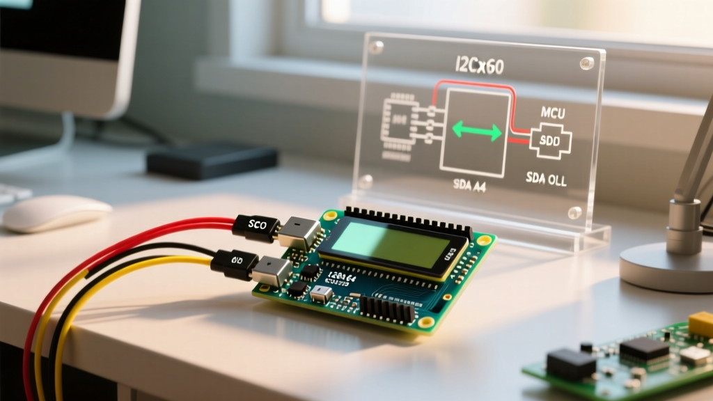
Wiring an OLED to Arduino via I2C requires connecting just four pins: VCC, GND, SCL, and SDA. However, the physical pin locations change depending on your microcontroller board. Below is the definitive wiring matrix for the most common AVR-based Arduino boards.
| OLED Pin | Arduino Uno / Nano (ATmega328P) | Arduino Mega 2560 | Arduino Leonardo (ATmega32U4) |
|---|---|---|---|
| GND | GND | GND | GND |
| VCC | 5V | 5V | 5V |
| SCL | A5 | D21 | D3 |
| SDA | A4 | D20 | D2 |
Pro-Tip for Sensor Integration: If you are daisy-chaining your OLED with a BME280 temperature sensor and a TSL2591 light sensor on the same I2C bus, ensure none of the modules share the exact same hardcoded I2C address. Use an I2C scanner sketch to verify unique addresses before soldering your final perf-board.
The 5V Logic Trap and Pull-Up Resistor Math
The most common reason an OLED fails to initialize on an Arduino isn't bad code; it's electrical noise and logic level mismatches. Most generic 0.96" OLED modules feature an onboard AMS1117-3.3 LDO regulator. This means you can safely feed them 5V on the VCC pin. However, the I2C data lines (SDA/SCL) on the ATmega328P operate at 5V logic, while the OLED controller expects 3.3V.
While many hobbyists get away with direct 5V-to-3.3V connections because the SSD1306 has internal clamping diodes, this violates the NXP I2C Bus Specification and can degrade the display's internal silicon over months of continuous operation. For industrial or long-term outdoor sensor nodes, use a bi-directional logic level converter (like the BSS138 MOSFET circuit) to shift the I2C lines down to 3.3V.
The Pull-Up Resistor Dilemma
I2C is an open-drain protocol. It requires pull-up resistors to pull the bus high. Most cheap OLED modules include 10kΩ surface-mount pull-up resistors on the PCB. If you are connecting multiple sensors, the parallel resistance drops. According to the official Arduino Wire library documentation, the internal AVR pull-ups are roughly 30kΩ to 50kΩ, which are far too weak for high-speed I2C.
- 1 to 2 devices on bus: The default 10kΩ on the OLED module is usually sufficient for 100kHz (Standard Mode).
- 3+ devices or long wires: Bus capacitance exceeds 100pF. The rise time of the I2C signal slows down, causing data corruption. You must add external 4.7kΩ or 2.2kΩ pull-up resistors to the 3.3V rail to sharpen the signal edges.
Memory Management: U8g2 vs. Adafruit_SSD1306
When integrating an OLED to Arduino, the choice of graphics library dictates how much SRAM you have left for your sensor polling routines. The ATmega328P has only 2KB of SRAM.
The popular Adafruit_SSD1306 library allocates a full-frame buffer. For a 128x64 display, this requires 1,024 bytes of contiguous SRAM (128 * 64 / 8). This instantly consumes 50% of your Arduino Uno's memory, leaving barely enough room for the Wire library buffers, String objects, and BME280 sensor data structs. This frequently leads to silent stack overflows and random reboots.
Instead, professional embedded engineers use the U8g2 Library. U8g2 offers a "Page Buffer" mode that only allocates a fraction of the screen in RAM (often less than 128 bytes) and renders the display in multiple passes. This leaves over 1.5KB of SRAM free for complex sensor fusion algorithms and JSON parsing.
Code Implementation: Rendering Sensor Data
Below is a production-ready snippet using U8g2 to read a simulated temperature value and render it to the OLED. Notice the use of the u8g2.firstPage() loop, which is mandatory for the memory-saving page buffer mode.
#include <Arduino.h>
#include <U8g2lib.h>
#include <Wire.h>

// Initialize U8g2 for SSD1306 128x64 I2C
U8G2_SSD1306_128X64_NONAME_F_HW_I2C u8g2(U8G2_R0, /* reset=*/ U8X8_PIN_NONE);

float simulatedTemp = 23.4;

void setup(void) {
  Wire.begin();
  u8g2.begin();
  u8g2.setFont(u8g2_font_helvB14_tr); // Bold 14pt font for sensor data
}

void loop(void) {
  // Simulate sensor polling delay
  delay(500);
  simulatedTemp += 0.1;
  if(simulatedTemp > 30.0) simulatedTemp = 20.0;

  // The Page Buffer Loop
  u8g2.firstPage();
  do {
    u8g2.setCursor(0, 20);
    u8g2.print("Room Temp:");

    u8g2.setFont(u8g2_font_logisoso24_tn); // Large 24pt numeric font
    u8g2.setCursor(10, 55);
    u8g2.print(simulatedTemp, 1);
    u8g2.print("\260C"); // Degree symbol + C
  } while ( u8g2.nextPage() );
}
Troubleshooting Matrix: Blank Screens and Artifacts
If you have verified your wiring but the screen remains black or displays static, consult this diagnostic matrix before replacing the hardware.
| Symptom | Root Cause | Hardware / Software Fix |
|---|---|---|
| Completely black, no backlight | Missing I2C pull-ups or dead LDO. | Measure VCC pin with multimeter. Ensure 3.3V is present on the controller chip. Add external 4.7k pull-ups. |
| Display shifted 2 pixels to the right | Module is actually an SH1106, not SSD1306. | Change library constructor from SSD1306 to SH1106. The SH1106 has a 132x64 RAM, requiring a 2px offset for 128x64 glass. |
| Random garbage pixels / flickering | I2C bus capacitance too high; signal rise time failing. | Shorten I2C wires to under 30cm. Lower I2C clock speed via Wire.setClock(10000); in setup(). |
| Screen freezes after 10 minutes | ATmega328P SRAM exhaustion (Stack Overflow). | Switch from Adafruit full-buffer to U8g2 page-buffer mode. Avoid using the String class in your loop. |
Mastering the connection of an OLED to Arduino requires looking past the basic pinout diagrams and respecting the electrical characteristics of the I2C bus. By selecting the correct controller, managing your pull-up resistors, and optimizing your SRAM with the U8g2 library, your sensor dashboards will achieve the reliability required for long-term deployment.