
Beyond the Basic Tutorial: Why the Datasheet Matters
Most tutorials for integrating an ir sensor arduino setup stop at three wires: VCC to 5V, GND to GND, and OUT to Digital Pin 11. While this might work on a messy breadboard in a dark room, it inevitably fails in real-world environments due to power rail noise, ambient light saturation, or protocol timing mismatches. To build reliable remote-controlled robotics, home automation interfaces, or media centers, you must understand the silicon. In this datasheet explainer, we dissect the industry-standard Vishay TSOP38238 and compare it against the ubiquitous generic VS1838B, translating dense engineering specifications into actionable wiring and coding rules.
Inside the Silicon: Architecture and the AGC Algorithm
An IR receiver module is not just a simple photodiode; it is a complex optoelectronic IC. According to the SB Projects IR Knowledge Base, modern 38kHz receivers contain three critical internal stages:
- PIN Photodiode: Converts incoming 940nm infrared light into a micro-current.
- Preamplifier & Bandpass Filter: Amplifies the signal and heavily filters out frequencies outside the 38kHz center frequency (±2kHz bandwidth).
- Automatic Gain Control (AGC): Dynamically adjusts the amplification threshold to suppress continuous noise sources like compact fluorescent lamps (CFLs) and modern LED room lighting.
The AGC is where most hobbyist projects fail. Vishay designs its AGC algorithms (like AGC2 and AGC3) to actively suppress continuous carrier waves. If your Arduino transmitter outputs a continuous 38kHz signal without pauses, the TSOP38238 will interpret it as ambient noise and mute its output pin. Your remote protocol must include gap times.
Datasheet Deep Dive: Critical Electrical Characteristics
Let us look at the hard numbers. Below is a comparison of the premium Vishay TSOP38238 and the generic VS1838B commonly found on KY-022 breakout boards.
| Parameter | Vishay TSOP38238 | Generic VS1838B |
|---|---|---|
| Supply Voltage (Vs) | 2.5V to 5.5V | 2.7V to 5.5V |
| Supply Current (Icc) | 0.35 mA (Typical) | 0.8 mA to 1.2 mA |
| Carrier Frequency | 38.0 kHz (±0.5kHz) | 37.9 kHz (High variance) |
| Output Voltage (Low) | ≤ 0.25V (Strong pull-down) | ≤ 0.4V |
| Typical Range (with 400 mW/sr emitter) | Up to 35 Meters | 8 to 12 Meters |
| 2026 Market Price (Single Unit) | ~$1.10 (Mouser/Digi-Key) | ~$0.15 (AliExpress/Amazon bulk) |
Datasheet Warning: The VS1838B has a notoriously wide frequency tolerance. If your Arduino transmitter uses the IRremote library to generate exactly 38.0kHz, a cheap VS1838B tuned to 36.5kHz will experience a 40% drop in reception range. Always measure your generic receiver's actual center frequency using an oscilloscope if range issues occur.
The Mandatory RC Filter: Do Not Skip the Capacitor
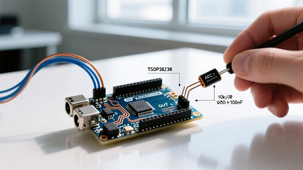
If you read page 6 of the Vishay TSOP38238 datasheet, you will see a mandatory application circuit featuring a 47Ω resistor and a 4.7µF electrolytic capacitor placed between the 5V rail and the sensor's VCC pin. Most hobbyists ignore this and wire VCC directly to the Arduino's 5V pin.
Why the RC Filter is Non-Negotiable
When an IR remote is pressed, the sudden optical pulse train causes the internal preamplifier to draw rapid, spiking current. Without the 4.7µF capacitor acting as a local energy reservoir, these micro-spikes inject high-frequency noise directly back into your Arduino's 5V rail. On boards with sensitive brown-out detection (like the Arduino Nano or ATmega328P-based custom PCBs), this power rail ripple can trigger spontaneous microcontroller resets or corrupt I2C bus communications running concurrently.
Actionable Wiring Rule: Always solder a 47Ω resistor in series with the 5V supply line, and place a 4.7µF capacitor from the sensor's VCC pin to GND, as close to the sensor pins as physically possible.
Optical Specifications and the 45-Degree Rule
The datasheet defines the "Relative Sensitivity" against the "Angle of Incidence." At 0 degrees (dead center), sensitivity is 100%. However, at 45 degrees off-axis, the sensitivity drops to roughly 50%. At 90 degrees, it plummets to near zero.
Furthermore, the datasheet specifies a minimum irradiance threshold. To achieve the advertised 35-meter range, your remote's IR LED must output at least 400 mW/sr (milliwatts per steradian). Standard TV remotes often output only 100 mW/sr, mathematically restricting your real-world range to about 12 meters, regardless of the sensor's quality. If you are building a custom Arduino IR transmitter using the Arduino IRremote Library, ensure you are driving a high-power TSAL6200 IR LED with a proper NPN transistor (like the 2N2222) to hit that 400 mW/sr threshold.
Protocol Timing: Minimum Burst Lengths
The AGC requires a minimum number of carrier cycles per burst to recognize a valid signal and drop the output pin LOW. The TSOP38238 datasheet specifies a minimum burst length of 10 cycles. At 38kHz, one cycle is 26.3 microseconds. Therefore, your transmitter must pulse the IR LED for at least 263µs continuously before the receiver will register it.
Conversely, the AGC requires a minimum gap time between bursts to reset its gain. If your protocol uses gaps shorter than 1.2 milliseconds, the receiver's AGC will assume the signal is continuous background noise (like a plasma TV emitting 38kHz interference) and will actively suppress the output. The standard NEC protocol solves this elegantly with a 9ms leading pulse burst followed by a 4.5ms space, perfectly satisfying the Vishay AGC reset requirements.
Real-World Failure Modes & Datasheet-Backed Fixes
- Sunlight Saturation: Direct sunlight contains massive amounts of broadband infrared. The datasheet notes that ambient illumination exceeding 40 mW/m2 at the 38kHz band will blind the PIN diode. Fix: Use an optical bandpass filter (a dark acrylic shield) or recess the sensor 5mm inside an opaque plastic housing to limit the field of view to 30 degrees.
- LED Room Light Interference: Modern PWM-dimmed LED bulbs often emit broadband IR noise that overlaps the 38kHz band. Fix: Switch to a Vishay TSOP34238, which utilizes a specialized AGC4 algorithm specifically tuned in 2024 to suppress PWM LED noise signatures.
- Logic Level Mismatch: While the TSOP38238 operates down to 2.5V, its output HIGH voltage is tied to its VCC pin. If you power the sensor with 5V but connect the output to a 3.3V ESP32 or Raspberry Pi Pico GPIO, you will fry the microcontroller pin. Fix: Power the sensor from the 3.3V rail (which is within the 2.5V-5.5V spec) or use a logic level shifter.
Summary
Treating an IR receiver as a simple digital switch is a recipe for intermittent failures. By respecting the TSOP38238 datasheet's mandates—specifically the RC power filter, the 10-cycle minimum burst length, and the 45-degree optical cone—you can transform a frustrating, unreliable ir sensor arduino prototype into a robust, commercial-grade interface. For further reading on protocol structures, the Adafruit IR Sensor documentation provides excellent companion code examples for decoding NEC and RC5 formats using modern microcontroller interrupt routines.