
Architecting High-RPM Speed Sensor Arduino Projects
Integrating a speed sensor with an Arduino microcontroller is a foundational skill for robotics, CNC machining, and automotive telemetry. However, as of 2026, the bottleneck in most speed sensor Arduino projects is rarely the hardware itself; it is the software driver architecture. Relying on basic polling loops (digitalRead() inside loop()) will inevitably lead to missed pulses and erratic RPM calculations once you exceed 3,000 RPM. To achieve industrial-grade reliability, you must leverage hardware interrupts, optimize Interrupt Service Routines (ISRs), and select the correct driver library for your specific sensor topology.
This guide bypasses basic wiring tutorials and dives deep into the library ecosystems, driver optimization, and edge-case troubleshooting required for professional-grade speed measurement using ATmega328P (Arduino Uno/Nano) and ESP32 architectures.
Hardware Selection Matrix: Matching Sensor to Application
Before writing a single line of driver code, you must match the sensor's output topology to your microcontroller's interrupt capabilities. Below is a comparison of the three most common speed sensors used in DIY and prototyping environments.
| Sensor Type | Typical Model | Output Signal | Max Reliable RPM | Approx. Cost (2026) | Best Use Case |
|---|---|---|---|---|---|
| Hall Effect (Digital) | KY-024 / A3144 | Single-Channel Pulse | 15,000 RPM | $1.50 - $3.00 | DC Motor speed, ABS wheel speed |
| IR Slotted Optointerrupter | FC-03 / LM393 | Single-Channel Pulse | 8,000 RPM | $2.00 - $4.00 | Conveyor belts, low-RPM gearboxes |
| Quadrature Encoder | Omron E6B2 / KY-040 | Dual-Channel (A/B) | 6,000+ RPM (Industrial) | $12.00 - $250.00 | Stepper feedback, CNC spindles, PID loops |
The Interrupt Architecture: Why Polling Fails
To understand why dedicated libraries are necessary, consider the math. A motor spinning at 6,000 RPM with a 20-tooth reluctor wheel generates 2,000 pulses per second (2 kHz). This means a pulse edge occurs every 500 microseconds (µs). A standard Arduino loop() executing serial prints, sensor reads, and math operations often takes 1,000 to 5,000 µs per iteration. Polling will physically miss the pulse edges.
The solution is hardware interrupts. According to the Arduino attachInterrupt() reference, hardware interrupts immediately pause the main program, execute the ISR, and resume. However, the ATmega328P only has two dedicated external interrupt pins (INT0 on D2, INT1 on D3). If you are building a multi-axis robot requiring four speed sensors, you must utilize Pin Change Interrupts (PCINT) or migrate to an ESP32, which supports interrupts on almost all GPIO pins.
Driver Guide 1: Quadrature Decoding with the PJRC Encoder Library
For quadrature encoders (like the Omron E6B2-CWZ6C), decoding the phase-shifted A and B channels manually in an ISR is prone to state-machine errors and switch bounce. The gold standard for this is the PJRC Encoder Library by Paul Stoffregen.
Optimizing the Library for High-Speed ISR Execution
By default, the library handles all edge cases, but this adds overhead. If you are strictly using hardware interrupt pins on an Arduino Uno, you can strip out the software polling fallbacks to reduce ISR latency. Add these macros at the very top of your sketch, before including the library:
#define ENCODER_USE_INTERRUPTS
#define ENCODER_OPTIMIZE_INTERRUPTS
#include <Encoder.h>

// Initialize on hardware interrupt pins 2 and 3
Encoder myEnc(2, 3);
This configuration forces the library to rely exclusively on hardware interrupts, dropping the ISR execution time to under 4 µs, allowing accurate tracking at speeds exceeding 20,000 RPM on standard hobby encoders.
Driver Guide 2: Custom Lean ISR for Single-Channel Hall Sensors
If you are using a simple single-channel Hall effect sensor (like the A3144) to measure the speed of a single DC motor, importing a massive quadrature library is a waste of flash memory and RAM. Writing a custom, lean driver is the professional approach.
The Atomic Read Problem
A common failure mode in custom speed sensor Arduino drivers is the 'torn read' glitch. An 8-bit AVR reads a 32-bit unsigned long variable in four separate 8-bit chunks. If an interrupt fires and increments the variable while the main loop is reading it, the main loop will read a corrupted, mathematically impossible value.
The Fix: You must disable interrupts momentarily during the read operation in the main loop. Here is the production-ready driver pattern:
volatile unsigned long pulseCount = 0;
volatile unsigned long lastMicros = 0;
unsigned long currentPulses = 0;
unsigned long pulseDuration = 0;

void setup() {
  pinMode(2, INPUT_PULLUP);
  attachInterrupt(digitalPinToInterrupt(2), pulseISR, FALLING);
  Serial.begin(115200);
}

void pulseISR() {
  unsigned long now = micros();
  pulseDuration = now - lastMicros;
  lastMicros = now;
  pulseCount++;
}

void loop() {
  // Atomic read block to prevent torn reads
  noInterrupts();
  currentPulses = pulseCount;
  unsigned long safeDuration = pulseDuration;
  interrupts();

  if (safeDuration > 0) {
    // Calculate RPM: (60,000,000 µs/min) / (µs per pulse * pulses per rev)
    float rpm = 60000000.0 / (safeDuration * 20.0); // 20-tooth wheel
    Serial.print('RPM: ');
    Serial.println(rpm);
  }
  delay(100); // Update rate
}
Expanding Interrupts: The PinChangeInterrupt Library
When you run out of pins D2 and D3 on an Arduino Nano, you must use PCINT. The native AVR registers for PCINT are notoriously difficult to configure manually. The PinChangeInterrupt library by NicoHood abstracts the register manipulation. It allows you to attach ISRs to pins D8-D13 and A0-A5.
Expert Warning: PCINT triggers on any state change (rising or falling) and groups pins into banks (e.g., PORTB). If multiple pins in the same bank trigger simultaneously, the ISR must query the PIN register to determine which specific pin caused the interrupt, adding roughly 2-3 µs of latency compared to dedicated hardware interrupts.
Real-World Troubleshooting & Edge Cases
Even with perfect code, real-world electromechanical environments introduce noise. Here is a troubleshooting matrix for common speed sensor anomalies.
| Symptom | Root Cause | Hardware Fix | Software Fix |
|---|---|---|---|
| RPM spikes randomly at low speeds | Switch bounce or EMI from nearby DC motors | Add a 100nF ceramic capacitor between Signal and GND; use external 4.7kΩ pull-up to 5V. | Implement a software debounce lockout in the ISR (ignore pulses < 50 µs apart). |
| RPM reads exactly half of actual speed | Triggering on both RISING and FALLING edges, or reading a quadrature encoder incorrectly. | Verify sensor datasheet for open-collector vs push-pull output. | Change attachInterrupt mode to strictly FALLING or RISING. |
| Microcontroller freezes at high RPM | ISR execution time exceeds pulse interval; stack overflow from nested interrupts. | N/A | Remove all Serial.print() and delay() from the ISR. Use flags to process data in loop(). |
| Phantom pulses when motor starts | Ground loops and voltage sag on the 5V rail during motor inrush. | Isolate sensor ground from motor power ground; use an optocoupler (e.g., 6N137) for signal isolation. | N/A |
Migration to ESP32: A 2026 Perspective
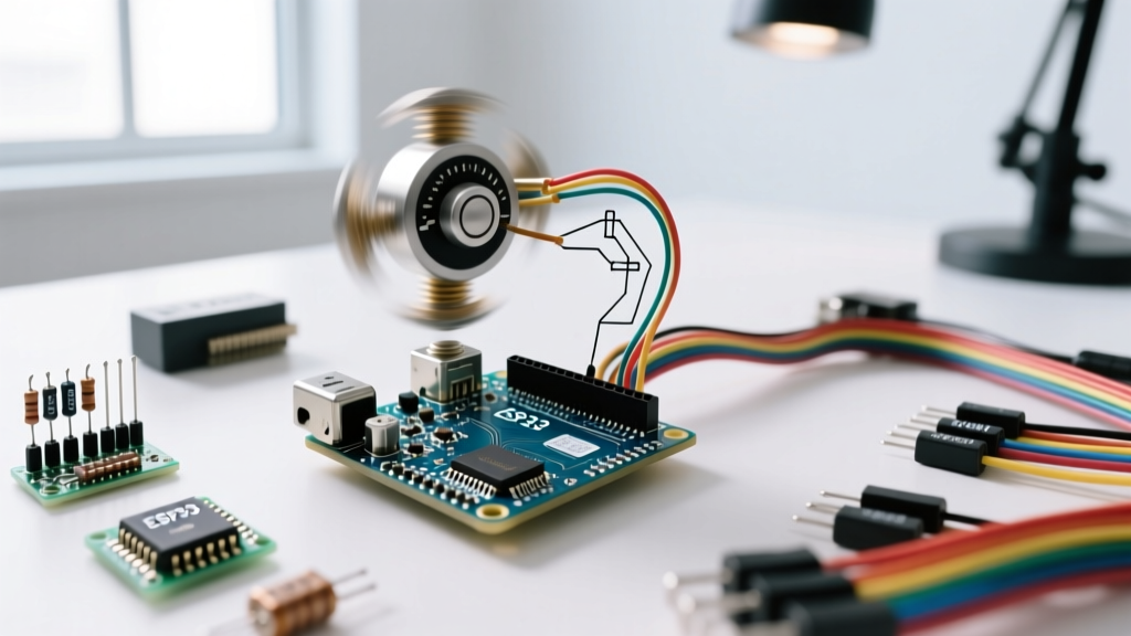
While the Arduino Uno remains a staple for education, modern 2026 builds heavily favor the ESP32 for speed sensing due to its MCPWM (Motor Control Pulse Width Modulation) and PCNT (Pulse Counter) hardware peripherals. The ESP32's PCNT module can count encoder pulses entirely in hardware without triggering a single CPU interrupt. This frees up the dual-core 240 MHz processor to handle Wi-Fi telemetry and complex PID kinematics while the hardware peripheral silently and accurately counts millions of pulses per second. If your project requires networked RPM telemetry or multi-axis synchronization, bypassing the ATmega328P in favor of the ESP32's hardware pulse counters is the most architecturally sound decision you can make.