
Introduction to Automotive Telemetry HUDs
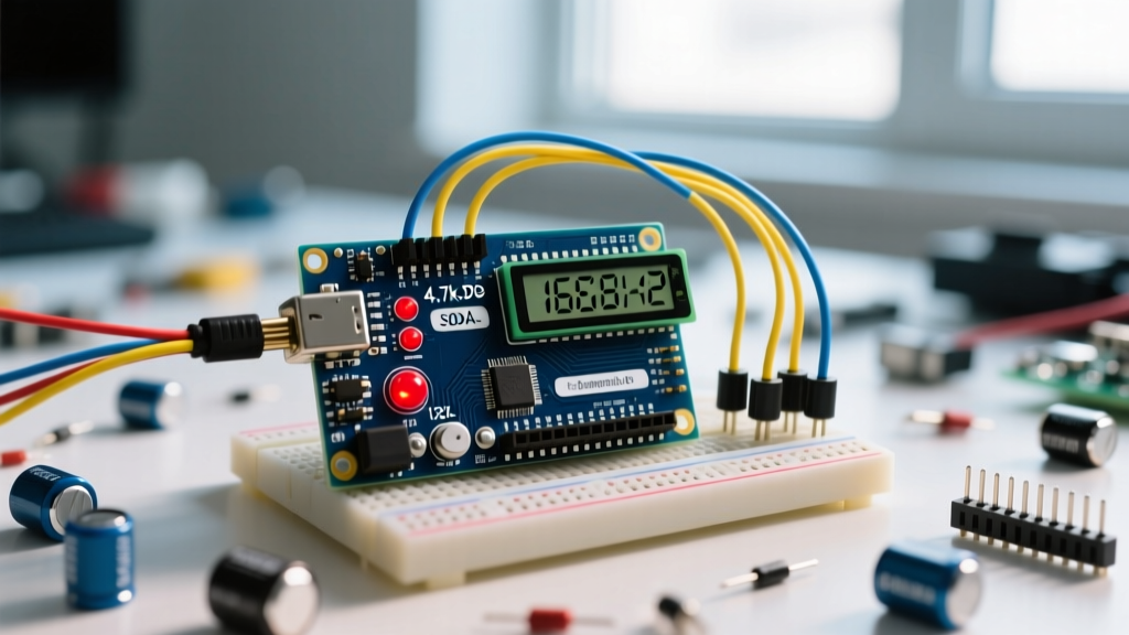
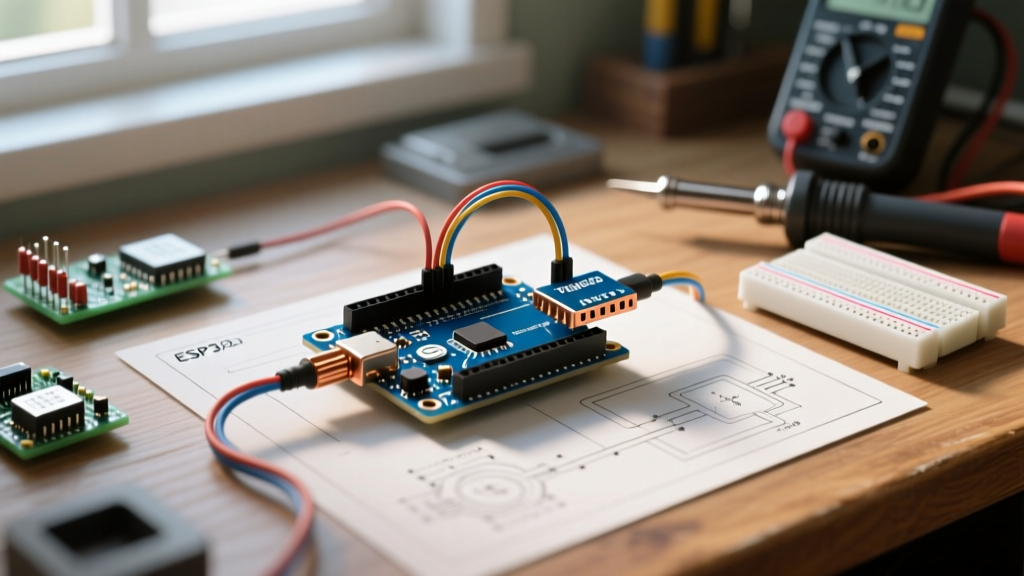
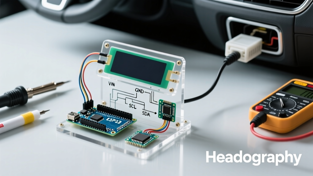
Building a custom Arduino head up display (HUD) is one of the most rewarding automotive DIY projects you can tackle. Unlike commercial $50 plug-and-play HUDs that suffer from washed-out LCDs and laggy CAN bus polling, a custom build allows you to extract exact OBD-II PIDs (Parameter IDs), filter the data, and project it onto a high-contrast combiner glass. In this 2026 guide, we will design a low-latency HUD using an Arduino Nano Every, an STN1110-based OBD-II UART adapter, and a high-brightness SPI OLED. We will cover the exact wiring schematics, automotive power safety, optical physics for the combiner, and the C++ code required to poll and mirror the telemetry.
Bill of Materials (2026 Pricing & Selection)
Component selection is critical for automotive environments. Cheap ELM327 clones often fail on modern ISO 15765-4 CAN networks or introduce 200ms+ latency. We use the STN1110 chip for reliable, high-speed UART communication.
| Component | Exact Model / Part Number | Est. Price | Purpose |
|---|---|---|---|
| Microcontroller | Arduino Nano Every (ABX00028) | $11.50 | 5V tolerant logic, ATmega4809 processor |
| OBD-II Adapter | SparkFun OBD-II UART (SEN-09555) | $54.95 | STN1110 chip, native CAN/ISO support |
| Display | Waveshare 1.5" RGB OLED (128x128) | $17.99 | SPI interface, high contrast for reflections |
| Power Supply | LM2596 Buck Converter Module | $3.50 | Steps 12V-14V car voltage down to 5.2V |
| Combiner Glass | 3mm Acrylic + Reflective HUD Film | $12.00 | Projects virtual image at focal distance |
Total Estimated Cost: ~$99.94
Automotive Power & Parasitic Draw Prevention
CRITICAL SAFETY WARNING: Never wire automotive electronics directly to the battery without an inline fuse and an ignition-switched trigger. Modern vehicles have sensitive CAN bus networks; improper back-feeding via the OBD-II port can trigger ECU faults or drain the battery in 48 hours.
To power the Arduino head up display safely, tap into an ignition-switched 12V source at the fuse box using an add-a-circuit fuse tap. Route this 12V line to the input of the LM2596 buck converter. Before connecting the Arduino, use a multimeter to adjust the LM2596 potentiometer to output exactly 5.2V. This slight over-voltage compensates for the voltage drop across the Nano Every's onboard Schottky protection diode, ensuring a stable 5V rail for the SPI OLED.
Parasitic Draw Edge Case: The OBD-II port provides constant 12V (Pin 16). If you power the STN1110 adapter directly from the port, it will keep the vehicle's CAN bus awake, resulting in a parasitic draw of 40-80mA, which will kill a standard lead-acid battery in a week. Always wire the OBD adapter's VCC to your ignition-switched buck converter output, not the OBD port's 12V pin.
Wiring Pinout Matrix & EMI Mitigation
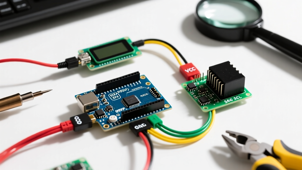
Cars are electrically noisy environments. The alternator and ignition coils generate massive Electromagnetic Interference (EMI). SPI lines running to the OLED are highly susceptible to this noise, which manifests as screen flickering or random pixel artifacts.
| Arduino Nano Every Pin | Destination | Wire Type / Notes |
|---|---|---|
| D1 (TX) | OBD-II UART RX | Twisted pair with ground |
| D0 (RX) | OBD-II UART TX | Twisted pair with ground |
| D13 (SCK) | OLED SCK | Add 33Ω series resistor |
| D11 (MOSI) | OLED DIN | Add 33Ω series resistor |
| D10 (SS) | OLED CS | Keep trace under 10cm |
| D9 | OLED DC | Standard jumper |
| D8 | OLED RST | Standard jumper |
Pro-Tip: The 33Ω series resistors on the SCK and MOSI lines act as termination resistors, dampening high-frequency ringing caused by the capacitance of the wires acting as antennas in the EMI-heavy dashboard environment.
Optics: The Combiner Physics
A true HUD doesn't just display an image on a screen; it creates a virtual image focused at infinity (or at least 2-3 meters ahead of the car). If you simply place an OLED on the dashboard, your eyes must constantly refocus between the road (far) and the screen (near), causing severe eye strain.
By angling a piece of acrylic coated with reflective HUD film at roughly 45 degrees, the light from the OLED bounces into your eyes while remaining transparent to the road ahead. Because the display is physically inverted and mirrored to achieve this bounce, we must handle the spatial transformation in the Arduino code. For optimal focal distance, mount the OLED exactly 15cm to 20cm away from the base of the combiner glass.
Arduino Code: Polling PIDs & Mirroring
We use the ELMduino Library Repository to handle the complex AT command handshakes and CAN framing. According to the CSS Electronics OBD-II PID Guide, standard PIDs like 0x0C (RPM) and 0x0D (Speed) are universally supported on post-2008 CAN vehicles.
Below is the optimized C++ implementation for the Nano Every. Notice the display.setRotation(2) and custom mirroring logic required to make the reflection readable through the combiner glass.
#include <ELMduino.h>
#include <Adafruit_GFX.h>
#include <Adafruit_SSD1351.h>

#define SCREEN_WIDTH 128
#define SCREEN_HEIGHT 128
#define CS_PIN 10
#define DC_PIN 9
#define RST_PIN 8

Adafruit_SSD1351 display(SCREEN_WIDTH, SCREEN_HEIGHT, CS_PIN, DC_PIN, RST_PIN);
ELM327 myELM327;

void setup() {
  Serial.begin(38400); // STN1110 default baud rate
  display.begin();
  display.fillScreen(0x0000); // Black background
  display.setRotation(2); // Flips for combiner reflection

  // Initialize OBD-II connection
  if (!myELM327.begin(Serial, true, 2000)) {
    display.setTextColor(0xF800); // Red
    display.println("OBD FAIL");
    while(1);
  }
}

void loop() {
  // Poll Vehicle Speed (PID 0x0D)
  float speed_kph = myELM327.kph();
  // Poll Engine RPM (PID 0x0C)
  float rpm = myELM327.rpm();

  display.fillScreen(0x0000);
  display.setTextColor(0x07FF); // Cyan for high contrast
  display.setTextSize(3);
  display.setCursor(10, 20);
  display.print((int)speed_kph);
  display.setTextSize(1);
  display.print(" KM/H");

  display.setCursor(10, 70);
  display.setTextSize(2);
  display.print((int)rpm);
  display.setTextSize(1);
  display.print(" RPM");

  delay(100); // 10Hz refresh rate prevents CAN bus flooding
}
Reference: For detailed STN1110 initialization sequences, consult the SparkFun OBD-II UART Hookup documentation.
Troubleshooting Automotive Edge Cases
- Screen Flickering at Idle: This is almost always caused by alternator ripple on the 12V line exceeding the LM2596's ripple rejection. Solder a 470µF low-ESR electrolytic capacitor and a 0.1µF ceramic capacitor in parallel across the 5V output rails of the buck converter.
- OBD Connection Timeouts: If the HUD fails to connect on startup, the vehicle's CAN bus may be in 'sleep' mode. Add a 1-second delay in the
setup()loop before callingmyELM327.begin()to allow the ECU to wake up after ignition. - Daylight Washout: The Waveshare RGB OLED outputs roughly 150 nits, which is excellent for night driving but struggles in direct noon sunlight. If daytime visibility is your priority, swap the OLED for a 2.0" ILI9225 TFT LCD (approx. 400 nits), but be aware you will need to modify the GFX library rotation parameters to account for the TFT's native controller orientation.
- CAN Bus Protocol Mismatch: Some older vehicles use ISO 9141-2 (K-Line) instead of CAN. The STN1110 auto-detects this, but it takes up to 30 seconds to handshake. If you know your car's protocol, hardcode it using
myELM327.sendCommand("ATSP 3")(for ISO 9141) to achieve instant boot times.
Final Calibration
Once the hardware is mounted, sit in the driver's seat with the engine running. Adjust the angle of the combiner glass until the virtual image appears to 'float' just above the hood of the car. Secure the acrylic with high-temperature automotive double-sided tape (like 3M VHB), as standard adhesives will fail when the dashboard reaches 60°C (140°F) in summer heat. Your custom Arduino head up display is now ready for the road.