
The Anatomy of a Failing PWM Signal
When your DC motors stutter, servos twitch erratically, or LEDs flicker instead of fading smoothly, the root cause is rarely a defective microcontroller. More often than not, the issue lies in how you are driving the pwm pins arduino boards provide. Pulse Width Modulation (PWM) is a digital emulation of an analog signal, achieved by toggling a pin HIGH and LOW at high frequencies. However, hardware limitations, software timer conflicts, and improper load management frequently disrupt this signal.
In this 2026 troubleshooting guide, we will dissect the most common failure modes of PWM on both the classic ATmega328P-based boards (Uno R3, Nano) and the modern Renesas RA4M1-based boards (Uno R4 Minima). By understanding the underlying architecture, you can eliminate signal degradation and build robust peripheral interfaces.
AVR (Uno R3/Nano) vs. Renesas (Uno R4) Architecture
Before debugging, you must know your hardware generation. The classic Arduino Uno R3 relies on the ATmega328P microcontroller, which utilizes hardware timers to generate PWM signals. It offers 6 PWM-capable pins (3, 5, 6, 9, 10, and 11) with an 8-bit resolution (0-255).
Conversely, the Arduino Uno R4 Minima uses a 32-bit Renesas RA4M1 ARM Cortex-M4 processor. While it maintains backward compatibility with the analogWrite() function, its native PWM resolution is 12-bit (0-4095), and it routes signals through a vastly different internal peripheral bus. Applying R3 troubleshooting logic to an R4 board will lead to dead ends, particularly regarding timer conflicts.
Symptom-to-Solution Diagnostic Matrix
Use the following matrix to quickly identify the root cause of your PWM anomalies based on the physical symptoms observed in your circuit.
| Symptom | Probable Root Cause | Actionable Fix |
|---|---|---|
| Motor whines loudly at low speeds | PWM frequency is within human hearing range (490Hz). | Reassign to pins 5 or 6 (980Hz), or change Timer1 prescaler to push frequency above 20kHz. |
| PWM works on pins 3/11, but fails on 9/10 | Software timer conflict (Timer1 hijacked by Servo.h). |
Move PWM load to Timer0 or Timer2 pins, or use a dedicated PCA9685 I2C PWM driver. |
| MOSFET overheats rapidly at partial duty cycles | Using non-logic-level MOSFET (e.g., IRF520) with 5V gate drive. | Replace with a true logic-level MOSFET like IRLZ44N or use a dedicated gate driver IC. |
| Microcontroller resets when motor starts | Inductive kickback or voltage sag on the 5V rail. | Add a Schottky flyback diode (1N5819) across motor terminals and isolate motor power supply. |
| Multimeter reads 2.5V instead of toggling 0-5V | Multimeter is averaging the DC duty cycle, not reading raw PWM. | Use an oscilloscope or a logic analyzer to verify the actual square wave signal. |
Hardware Pitfalls: Current Sourcing and Inductive Kickback
One of the most pervasive mistakes in DIY electronics is attempting to drive inductive loads (like DC motors or solenoids) directly from a microcontroller pin, or even through an improperly chosen transistor.
The MOSFET Gate Capacitance Trap
When using PWM to control a high-power load, you typically switch a MOSFET. Beginners frequently reach for the IRF520 MOSFET because it is ubiquitous in cheap starter kits. However, the IRF520 is not a logic-level MOSFET. Its gate-source threshold voltage (Vgs(th)) is listed as 2.0V to 4.0V, but it requires 10V on the gate to fully turn on and achieve its rated low Rds(on) resistance.
When driven by a 5V Arduino PWM pin, the IRF520 lingers in its linear (partially on) region. During PWM transitions, the gate capacitance (approx. 350pF) charges and discharges slowly without a dedicated gate driver. This causes the MOSFET to dissipate massive amounts of heat, leading to thermal shutdown or catastrophic failure, which manifests as a stuttering or dying motor.
- The Fix: Always use true logic-level MOSFETs for 5V microcontrollers. The IRLZ44N or STP16NF06L are fully enhanced at Vgs = 4.5V. For high-frequency PWM (above 10kHz), add a push-pull gate driver like the TC4427 to rapidly charge and discharge the gate capacitance, ensuring crisp square waves.
Inductive Kickback and Flyback Diodes
When you turn off a DC motor via PWM, the collapsing magnetic field in the motor coils generates a massive reverse voltage spike (inductive kickback). If unclamped, this spike travels back through the MOSFET and into the Arduino's ground plane, causing brownouts, erratic behavior on other PWM pins, or permanent silicon damage.
Expert Tip: Always place a flyback diode in parallel with inductive loads. While the standard 1N4007 silicon diode works for low-frequency applications, its reverse recovery time is too slow for high-speed PWM. For frequencies above 1kHz, use a Schottky diode like the 1N5819 or SS34, which offers near-instantaneous clamping.
Software Conflicts: Timers, Tones, and Servos
On 8-bit AVR boards (Uno R3, Nano, Mega2560), the analogWrite() function relies on hardware timers. There are only three 8-bit/16-bit timers available for standard PWM generation, and they are shared with core Arduino libraries.
The Timer Collision Matrix
If your PWM signal suddenly flatlines or defaults to fully ON/OFF, check your included libraries against this AVR timer map:
- Timer0 (Pins 5, 6): Tied to
millis(),delay(), andmicros(). Altering the prescaler on Timer0 to change PWM frequency will break all timekeeping functions in your sketch. Never change Timer0 prescalers unless you are rewriting the Arduino core timing. - Timer1 (Pins 9, 10): A 16-bit timer. If you include the standard
Servo.hlibrary, it hijacks Timer1 to generate the 50Hz pulse train required by hobby servos. Result: PWM on pins 9 and 10 is instantly disabled. - Timer2 (Pins 3, 11): An 8-bit timer. If you use the
tone()function to drive a piezo buzzer, it monopolizes Timer2. Result: PWM on pins 3 and 11 ceases to function untilnoTone()is called.
For a deeper dive into how these hardware registers operate, refer to the official Secrets of Arduino PWM documentation, which details direct register manipulation to bypass standard library limitations.
Measuring PWM: Why Your Multimeter is Lying to You
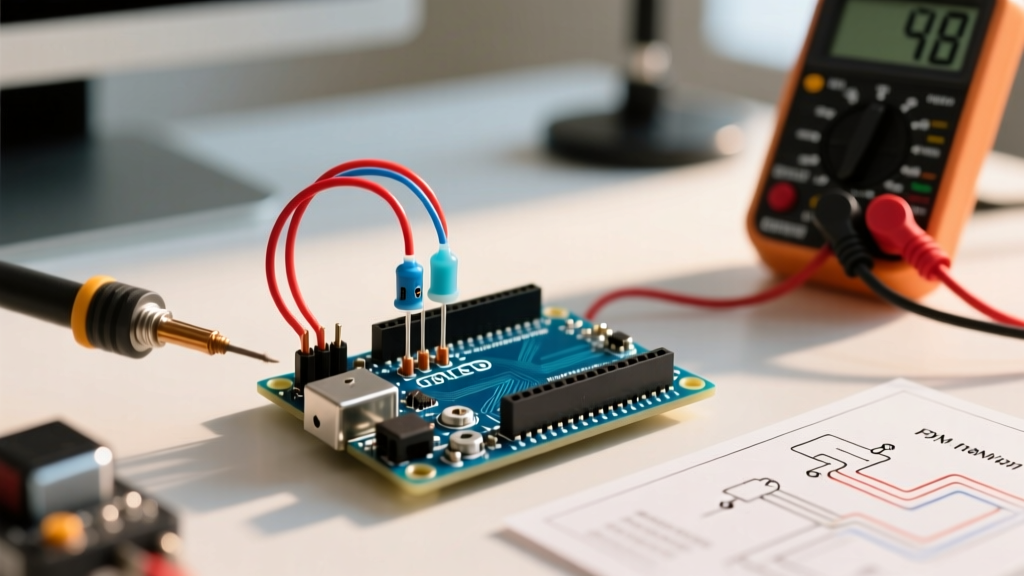
A frequent troubleshooting dead-end occurs when a maker uses a standard digital multimeter (DMM) to verify a PWM pin. If you set your analogWrite(pin, 127) (a 50% duty cycle on a 5V logic system) and probe the pin with a DMM in DC voltage mode, the meter will likely display ~2.5V.
This leads many to incorrectly assume the Arduino is outputting a true analog voltage or that the pin is damaged. In reality, the DMM's sampling rate is far too slow to catch the 490Hz or 980Hz switching; it merely averages the voltage. To properly troubleshoot PWM pins, you must use an oscilloscope or a USB logic analyzer (like the Saleae Logic Pro or a generic $15 CY7C68013A clone) to visualize the actual duty cycle and verify the rising/falling edge integrity.
Advanced Fixes: Reassigning Timers and Prescalers
If your application requires ultrasonic PWM (above 20kHz) to eliminate audible motor whine, or if you need to synchronize multiple PWM channels, you must manipulate the timer prescalers directly via C++ bitwise operations.
For example, to increase the PWM frequency on Timer1 (Pins 9 and 10) to approximately 31.37kHz on an Uno R3, you bypass the Arduino bootloader's default settings and write directly to the Timer/Counter Control Register B (TCCR1B):
// Clear Timer1 prescaler bits
TCCR1B &= ~( (1<
As outlined in SparkFun's comprehensive guide to PWM, altering prescalers yields massive performance gains for DC motor control, but requires careful calculation to ensure the resulting frequency doesn't exceed the switching limits of your external MOSFETs or motor driver ICs.
Migrating to the Uno R4? Use 12-Bit Resolution
If you have upgraded to the Arduino Uno R4 Minima or WiFi, you are no longer bound by 8-bit AVR limitations. The Renesas RA4M1 supports up to 12-bit PWM resolution natively. To utilize this for ultra-smooth LED fading or precision DAC-like control, you must explicitly call analogWriteResolution(12); in your setup() block. This expands your duty cycle range from 0-255 to 0-4095, providing 16 times the granularity for sensitive peripheral control. For complete syntax and peripheral routing on the R4 architecture, consult the official analogWrite() language reference.
Final Troubleshooting Checklist
- Verify Pin Capability: Ensure you are not calling
analogWrite()on a strictly digital pin (like Pin 13 on the Uno R3, which lacks hardware PWM). - Check Library Conflicts: Audit your code for
Servo.h,tone(), or third-party libraries likeIRremotethat silently hijack hardware timers. - Inspect the Gate Drive: Confirm your MOSFET is logic-level and that the gate is being pulled to ground via a 10kΩ resistor when the Arduino pin is floating.
- Clamp Inductive Spikes: Verify the physical orientation of your flyback diode (cathode to positive, anode to negative).
By systematically isolating the hardware, software, and physical load variables, you can transform erratic PWM signals into precise, reliable control mechanisms for any sensor or peripheral project.