
Anatomy of a 4-Digit 7-Segment Display
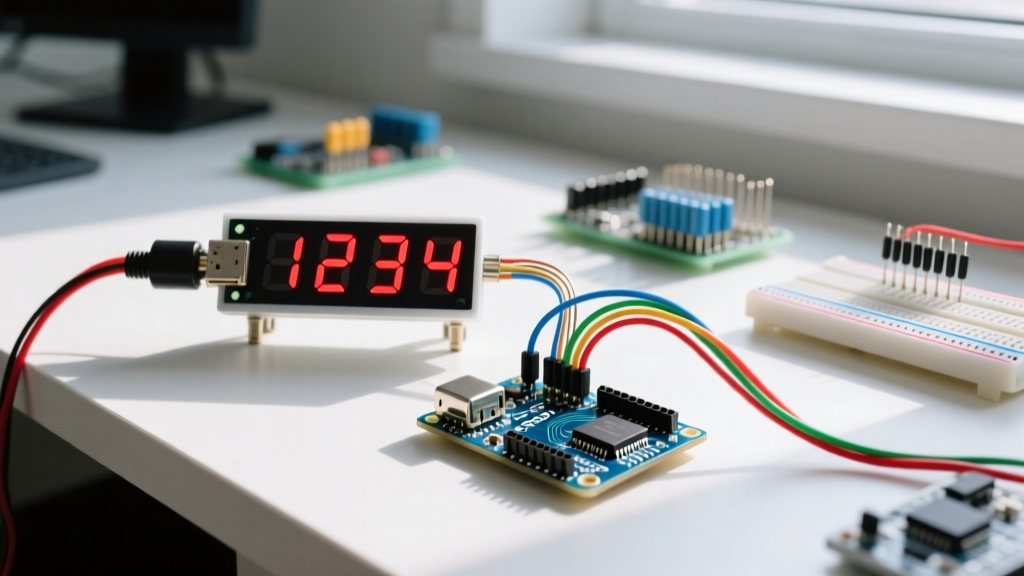
Integrating a 7 segment 4 digit display Arduino setup is a rite of passage for embedded systems engineers. Unlike single-digit modules, a 4-digit display (commonly sold as the 3461AS or 3461BS) utilizes a 12-pin architecture. Instead of requiring 32 individual GPIO pins (8 segments × 4 digits), the display uses a multiplexed matrix. Eight pins control the individual segments (A through G, plus the decimal point), while the remaining four pins act as common cathodes or anodes for each digit.
To display a 4-digit number like "1984", the microcontroller does not power all digits simultaneously. Instead, it rapidly cycles through each digit, illuminating the correct segments for a few milliseconds before moving to the next. This technique, known as persistence of vision multiplexing, tricks the human eye into perceiving a continuous, steady readout. However, executing this flawlessly requires precise timing, correct current limiting, and the right software library.
Hardware Comparison Matrix: Bare vs. Integrated Drivers
Before wiring your breadboard, you must choose your hardware approach. In 2026, makers generally choose between bare displays, TM1637-based modules, or MAX7219 modules. Below is a technical comparison to guide your component selection.
| Module Type | GPIO Pins Required | MCU CPU Overhead | Avg. Price (2026) | Best Use Case |
|---|---|---|---|---|
| Bare 3461AS/BS (Direct) | 12 Pins | High (Requires constant refresh loop) | $1.50 - $2.50 | Custom PCBs, tight BOM budgets |
| TM1637 Module | 2 Pins (CLK, DIO) | Negligible (Hardware handles refresh) | $2.00 - $3.50 | General projects, ESP32/Arduino |
| MAX7219 Module | 3 Pins (SPI) | Negligible (SPI hardware refresh) | $4.50 - $7.00 | High-precision, daisy-chaining |
Wiring Bare Modules: The Transistor Imperative
The most common and destructive mistake beginners make when wiring a bare 7 segment 4 digit display Arduino project is connecting the common digit pins directly to the microcontroller's GPIO pins. Let us look at the math:
- A standard red LED segment requires roughly 15mA to 20mA for optimal brightness.
- If you display the number "8" (all 7 segments plus the decimal point active), a single digit draws 160mA (8 × 20mA).
- The ATmega328P (Arduino Uno R3) and the R7FA4M1 (Uno R4) have an absolute maximum current rating of 40mA per I/O pin, and a 200mA limit for the VCC/GND rails.
Expert Warning: Driving a common digit pin directly from an Arduino GPIO while displaying an '8' will permanently fry the microcontroller's internal bond wires. You must use external switching transistors.
The Correct Bare Wiring Topology
For a Common Cathode display (e.g., 3461AS), use NPN transistors like the 2N3904. For a Common Anode display (e.g., 3461BS), use PNP transistors like the 2N3906.
- Segment Pins (8 total): Connect each to an Arduino digital pin through a 220Ω current-limiting resistor. Assuming a 5V logic level and a 2.0V forward voltage drop for red LEDs, 220Ω safely limits current to ~13.6mA per segment.
- Digit Pins (4 total): Connect each to the collector of a 2N3904 transistor. The emitter goes to GND.
- Base Resistors: Place a 1kΩ resistor between the Arduino GPIO and the transistor base to limit base current.
- Pull-down Resistors: Add a 10kΩ resistor between the transistor base and GND. This prevents "ghosting" by ensuring the transistor stays fully off when the GPIO is in a high-impedance state during boot-up.
Driving Bare Displays with the SevSeg Library
Writing a non-blocking multiplexing routine from scratch is tedious and prone to timing errors. The industry standard for bare displays is the SevSeg Library by Dean Reading. This library handles the persistence of vision timing using hardware timer interrupts or a highly optimized millis() polling loop.
Configuration and Edge Cases
When initializing SevSeg, you must define your hardware topology accurately. A common edge case occurs when developers use the COMMON_CATHODE constant but wire a COMMON_ANODE display, resulting in inverted logic where unlit segments glow and lit segments turn off.
Furthermore, if your project utilizes other libraries that rely on Timer1 or Timer2 (such as the standard Servo.h library or certain IR remote receivers), SevSeg's hardware interrupt mode will cause a fatal conflict. In these scenarios, you must configure SevSeg to use software polling. This requires you to call sevseg.refreshDisplay(); inside your main loop() at least once every 1-2 milliseconds. If you use blocking code like delay(100), the display will freeze or flicker violently.
The TM1637 Alternative: Offloading the MCU
If your project requires complex multitasking, WiFi communication, or audio processing, dedicating CPU cycles to display multiplexing is inefficient. The TM1637 driver IC solves this by integrating the multiplexing matrix and LED current sinks into a single chip, communicating via a custom 2-wire protocol.
Using the highly reliable TM1637Display Library by Avishay Orpaz, you only need to connect the CLK and DIO pins to any two digital GPIOs. Because the TM1637 features internal RAM and a hardware refresh oscillator, the Arduino only sends data when the displayed value changes. Once the data is transmitted, the MCU is entirely free to handle other tasks.
Brightness Control and Colon Blinking
The TM1637 allows for 8 levels of PWM brightness control. A frequent mistake is calling setBrightness(8), which actually exceeds the 0-7 index bounds and causes undefined behavior or display blanking. Always use values between 0 (darkest) and 7 (brightest). Additionally, the library supports manipulating the decimal point pins to simulate a blinking colon for clock applications via the showNumberDecEx() method with specific bitmask arguments.
Advanced Troubleshooting & Edge Cases
Even with the correct library, environmental and hardware factors can degrade display performance. Here is how to diagnose the most common failure modes:
- Ghosting (Faint illumination of unlit segments): This occurs due to parasitic capacitance in the breadboard or slow transistor switching speeds. Fix: Ensure the 10kΩ base pull-down resistors are installed. If using a breadboard, keep segment wires under 3 inches to reduce capacitance.
- Uneven Brightness Across Digits: If digit '1' appears brighter than digit '4', your multiplexing loop is spending unequal time on each digit, or the ground path resistance is too high. Fix: Use a dedicated ground bus wire rather than daisy-chaining grounds through breadboard rails.
- ESP32 WiFi Flickering: When using an ESP32, the WiFi radio's interrupt service routines (ISRs) can preempt the software polling loop of the SevSeg library, causing visible flickering. Fix: Assign the SevSeg refresh task to Core 0 using FreeRTOS, or switch to a TM1637 hardware-driven module.
Frequently Asked Questions
Can I use an Arduino Uno R4 WiFi for direct multiplexing?
Yes, but the R4 Minima/WiFi operates at 5V logic on its standard headers, making it compatible with standard 5V 2N3904 transistor circuits. However, the R4's Renesas RA4M1 processor handles GPIO toggling differently than the ATmega328P. Ensure you are using the latest version of the SevSeg library, as older versions hardcoded AVR-specific timer registers that will fail to compile on ARM Cortex-M4 architectures.
Why do my blue/white displays look incredibly dim?
Blue and white LEDs have a forward voltage (Vf) of roughly 3.2V, compared to 2.0V for red. If you are powering your Arduino via USB (which often sags to 4.6V), the voltage differential across a 220Ω resistor is only 1.4V, yielding a meager 6mA of current. Fix: Drop the segment resistors to 100Ω for blue/white displays, or power the display's common pins from a dedicated 5V/12V external supply.
For deeper insights into managing microcontroller timing conflicts when multiplexing, refer to the official Arduino documentation on timer interrupts. Understanding how hardware timers interact with your display driver is the key to achieving a rock-solid, flicker-free readout in any embedded project.