
Diagnostic Matrix: Identifying Touch Sensor Arduino Faults
Capacitive touch sensors offer a sleek, solid-state alternative to mechanical switches, but they are notoriously sensitive to environmental noise. Whether you are using a basic single-channel TTP223 module (typically around $0.40 in 2026) or a sophisticated 12-channel I2C MPR121 breakout ($3.50 to $8.00), 'ghost touches' and unresponsive pads can derail a project. Before rewriting your code, use this diagnostic matrix to isolate the hardware or physical layer fault.
| Symptom | Probable Root Cause | Hardware / Software Fix |
|---|---|---|
| Constant HIGH output (Stuck ON) | Floating ground, missing pull-down, or dielectric touching bare copper. | Verify GND continuity to Arduino. Ensure no bare wire strands touch the sensor pad. |
| Random 'Ghost Touches' (Erratic triggers) | Electromagnetic Interference (EMI) from nearby PWM lines, motors, or AC mains. | Route touch traces away from high-current wires. Add 100nF decoupling capacitor at VCC/GND. |
| No response through enclosure | Dielectric panel is too thick or has a low dielectric constant ($k$). | Reduce panel thickness to under 3mm, or switch from wood to glass/acrylic. |
| Touch works, but Release is delayed | Software debounce threshold set too high or parasitic capacitance drift. | Adjust MPR121 release threshold registers or lower TTP223 sensitivity capacitor. |
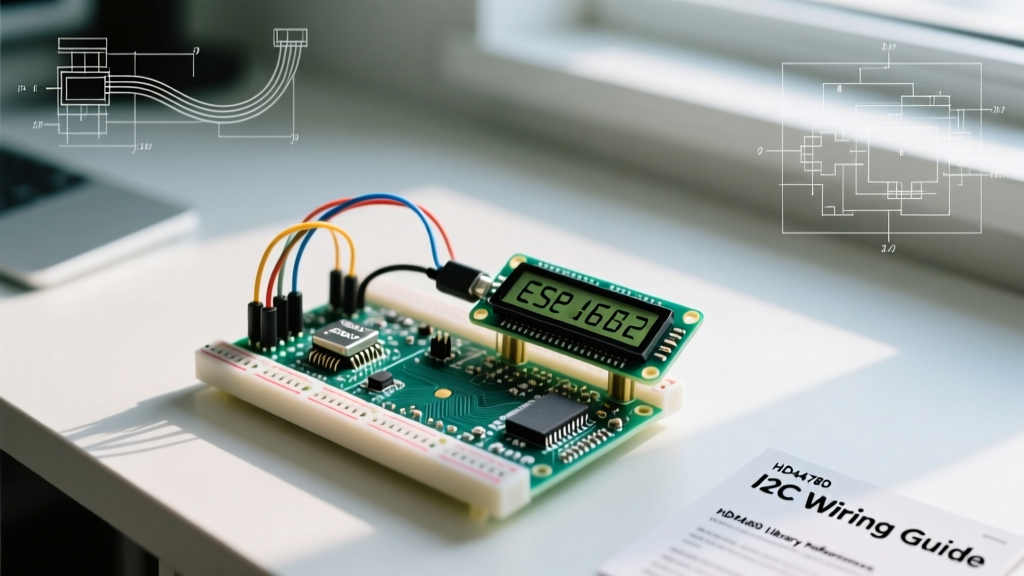
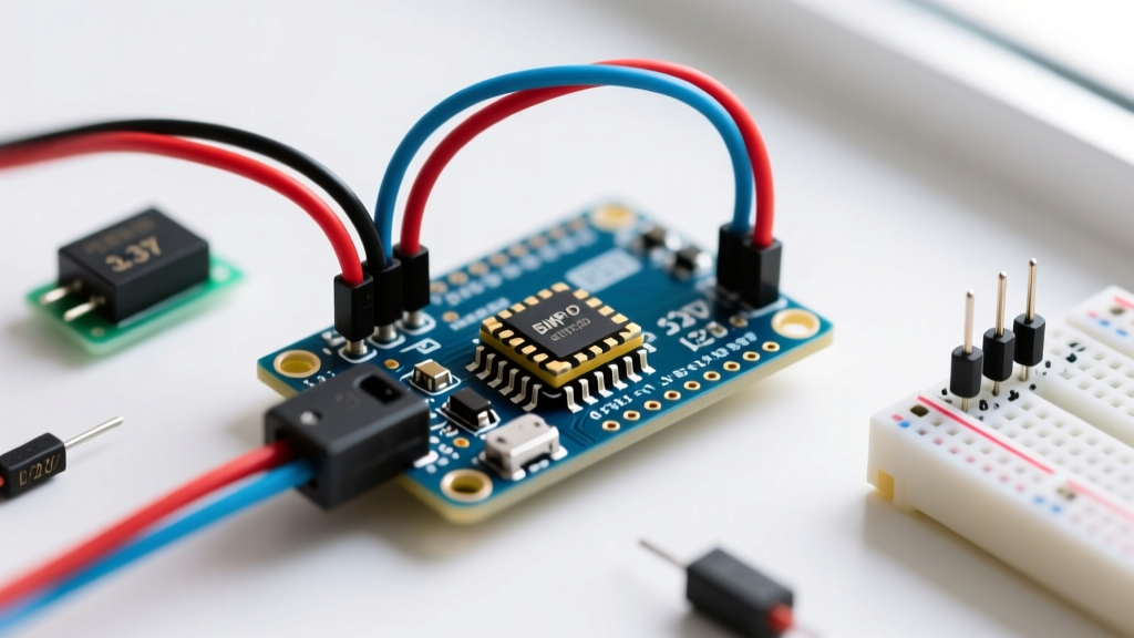
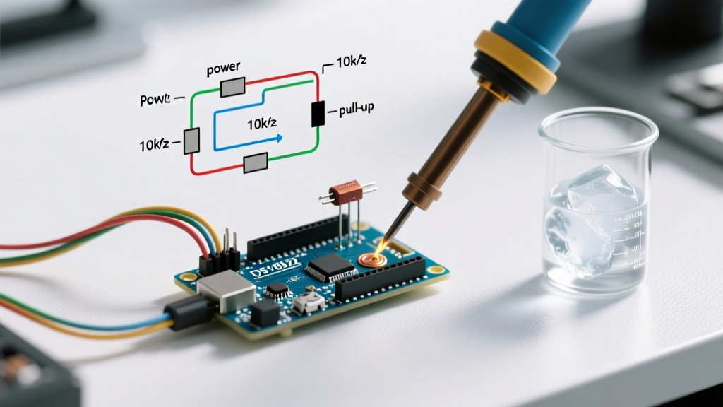
| I2C Bus Lockups (MPR121 only) | Missing pull-up resistors or bus capacitance exceeding 400pF. | Add 4.7kΩ pull-ups to SDA/SCL. Keep I2C wire length under 12 inches. |
1. Power Supply Noise and Grounding Loops
The most common culprit for erratic touch sensor Arduino behavior is 'dirty' power. Capacitive sensing relies on measuring picofarad (pF) changes in capacitance. A noisy 5V rail from a standard USB power bank can introduce millivolt-level ripple that the sensor's internal oscillator interprets as a finger touch.
The TTP223 'Dirty Power' Vulnerability
In 2026, the market remains saturated with ultra-cheap TTP223 clone modules. Many of these cost-optimized boards omit the recommended 100nF ceramic decoupling capacitor across the VCC and GND pins. If your Arduino is powering a motor shield or LED strip on the same 5V rail, the voltage sag will trigger false positives.
- The Fix: Solder a 100nF (0.1μF) ceramic capacitor directly across the VCC and GND pins on the sensor module. Keep the leads as short as physically possible to minimize parasitic inductance.
- Isolation: For high-noise environments, power the touch sensor from the Arduino's 3.3V pin (if the module supports 2.5V-5.5V operation) or use a dedicated LDO voltage regulator like the AMS1117-3.3 to isolate it from 5V motor noise.
2. Dielectric Selection and Parasitic Capacitance
A touch sensor does not detect physical pressure; it detects the change in capacitance when a conductive object (your finger) approaches the electrode through a dielectric material. The thickness and material of your enclosure drastically alter the baseline parasitic capacitance.
Material Thickness Limits for Reliable Triggering
According to capacitive sensing design guidelines from SparkFun's MPR121 Hookup Guide, the dielectric constant ($k$) of your overlay dictates the maximum allowable thickness. If your enclosure is too thick, the sensor's baseline capacitance will max out its internal registers, rendering it blind to additional finger capacitance.
| Material | Dielectric Constant ($k$) | Max Recommended Thickness | Notes |
|---|---|---|---|
| Glass | 4.0 - 10.0 | 5.0 mm | Excellent for rigid UI panels; high sensitivity. |
| Acrylic (PMMA) | 2.8 - 3.2 | 3.0 mm | Most common for 3D printed / laser-cut enclosures. |
| PLA / ABS (3D Printed) | 2.5 - 2.9 | 2.5 mm | Infill density and air gaps can cause uneven sensing. |
| Wood (MDF/Plywood) | 1.5 - 2.5 | 1.5 mm | Highly susceptible to humidity changes; not recommended. |
Pro-Tip for 3D Printed Enclosures: If you must use a thick PLA case, design a 'dimple' or recessed pocket on the inside of the print, leaving only 1mm of material directly over the copper touch pad. This maintains structural integrity while putting the sensor within the optimal capacitive range.
3. Electromagnetic Interference (EMI) from Peripherals
When integrating a touch sensor into a larger Arduino project involving relays, servos, or WS2812B addressable LEDs, EMI becomes a massive factor. Fast-switching digital signals and PWM lines radiate electromagnetic fields that couple into the high-impedance touch electrodes.
Routing and Shielding Best Practices
- Trace Routing: Never route a touch electrode trace parallel to a PWM or high-current DC line. If they must cross, force them to intersect at a strict 90-degree angle to minimize capacitive coupling.
- The Guard Ring Technique: For custom PCBs or copper tape layouts, surround the touch pad with a 'guard ring' connected to a dedicated microcontroller pin driven with the exact same waveform as the sensor's charge/discharge cycle. This effectively cancels out parasitic fringe capacitance from the surrounding environment.
- Twisted Pair I2C: If using the MPR121, the I2C bus is vulnerable to noise. Use twisted-pair wiring for SDA and SCL lines, and ensure your 4.7kΩ pull-up resistors are located physically close to the Arduino's microcontroller, not the sensor end.
4. Software Threshold Tuning (MPR121 Deep Dive)
While the TTP223 handles thresholding via a single surface-mount capacitor (labeled 'Cj' on the board), the MPR121 offers granular software control via I2C registers. If your hardware is sound but the sensor is still misbehaving, you must tune the Analog Front End (AFE) registers.
As detailed in the official NXP MPR121 Datasheet, the sensor compares the measured electrode capacitance against two thresholds: Touch and Release. This hysteresis prevents oscillation when a finger hovers at the edge of the detection field.
Crucial MPR121 Registers for Debouncing
- Touch Threshold (Registers 0x41 - 0x58): Lower values increase sensitivity. If you are getting ghost touches, increase this value (e.g., from 0x0F to 0x15).
- Release Threshold (Registers 0x42 - 0x5A): Must be lower than the Touch threshold. A wider gap between Touch and Release creates stronger hysteresis, curing 'flickering' states.
- Debounce Register (0x2B): This register dictates how many consecutive samples must cross the threshold before an interrupt is triggered. Setting the upper nibble (release debounce) to 4 or 8 samples will eliminate micro-second EMI spikes.
Tuning the TTP223 Hardware Jumper
If you are strictly using the TTP223, you lack software registers, but you do have hardware pads. On the back of the module, you will find two sets of unpopulated solder pads:
- Pads '0' and '1' (Trigger Mode): By default, the output goes HIGH only while the pad is touched (momentary). Bridging pad '1' with solder changes this to a toggle switch (flip-flop) mode.
- Pads 'A' and 'B' (Active State): Bridging pad 'A' makes the default output LOW. Bridging pad 'B' makes the default output HIGH. Ensure this matches your Arduino
digitalRead()logic expectations.
5. Environmental Factors: Humidity and Thermal Drift
Capacitive sensors are inherently environmental sensors. Water has a dielectric constant of roughly 80, making it highly conductive to capacitive fields. If your Arduino project is deployed in a greenhouse, kitchen, or outdoor enclosure, condensation on the dielectric surface will register as a massive, continuous finger touch.
Weatherproofing Your Touch Interface
To combat humidity drift, consider the following mitigation strategies based on Adafruit's capacitive sensing best practices:
- Conformal Coating: Apply a thin layer of acrylic conformal coating or clear nail polish over exposed copper tape pads to prevent direct moisture contact and oxidation.
- Auto-Calibration on Boot: The MPR121 features a built-in auto-calibration routine that runs on power-up or when triggered via the AFE configuration register. Ensure your Arduino code delays for at least 200ms after power-on before initializing the I2C bus, allowing the sensor's internal baseline tracking to stabilize to the current ambient humidity.
- Drainage Channels: If designing a custom 3D-printed faceplate, machine a micro-groove (0.5mm deep) around the perimeter of the touch zone to wick away condensation via capillary action.
Summary Checklist for the Workbench
Before throwing away a 'faulty' touch sensor module, run this final checklist:
- [ ] Is a 100nF decoupling capacitor soldered directly at the module's VCC/GND?
- [ ] Are high-current/PWM wires routed at least 2 inches away from the touch pads?
- [ ] Is the dielectric overlay less than 3mm thick (for acrylic/PLA)?
- [ ] Have I2C pull-up resistors (4.7kΩ) been verified with a multimeter?
- [ ] Is the software debounce threshold configured to ignore sub-millisecond noise spikes?
By methodically addressing power integrity, dielectric physics, and EMI routing, you can transform a frustrating, erratic touch interface into a robust, commercial-grade input system for your Arduino projects.