
The Anatomy of Servo PWM Signals
Before diving into the code, it is critical to understand how RC servos interpret electrical signals. Unlike standard DC motors, servos rely on Pulse Width Modulation (PWM) at a strict 50Hz frequency (a 20-millisecond period). The position of the servo horn is dictated by the duration of the HIGH pulse within that 20ms window.
- 500µs (0.5ms): Typically 0 degrees (fully counter-clockwise)
- 1500µs (1.5ms): 90 degrees (center position)
- 2500µs (2.5ms): 180 degrees (fully clockwise)
While the official standard dictates 1000µs to 2000µs for 0-180 degrees, most modern micro-servos like the TowerPro SG90 actually respond to a wider 500µs-2400µs range. When you learn to code servo Arduino projects, accounting for these physical microsecond boundaries prevents gear stripping and current spikes.
Method 1: The Native <Servo.h> Library (Quick & Simple)
For basic projects requiring one to twelve servos, the built-in Arduino Servo library is the fastest route. According to the Arduino Servo Library Reference, this library abstracts the complex timer interrupts required to generate the 50Hz signal.
Basic Sweep Implementation
#include <Servo.h>

Servo myServo;

void setup() {
  // Attach servo to Pin 9.
  // We explicitly define the min/max microsecond pulse widths to prevent gear grinding.
  myServo.attach(9, 500, 2400);
}

void loop() {
  myServo.write(0);   // Move to 0 degrees
  delay(1500);
  myServo.write(90);  // Move to center
  delay(1500);
  myServo.write(180); // Move to 180 degrees
  delay(1500);
}
The Timer1 Conflict Trap
There is a hidden hardware cost to using <Servo.h> on ATmega328P-based boards (like the Uno or Nano). The library hijacks Timer1 to generate the 50Hz interrupts. Consequently, the hardware PWM functionality on Pins 9 and 10 is disabled. If your project requires dimming an LED or driving a DC motor via analogWrite() on those pins while simultaneously running a servo, your circuit will fail silently or output a digital HIGH/LOW instead of a PWM wave.
Method 2: PCA9685 I2C Driver (Professional Grade)
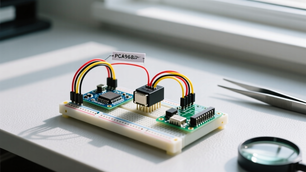
For robotics, hexapods, or robotic arms requiring 16+ servos without taxing the microcontroller's CPU or timers, the NXP PCA9685 I2C PWM driver is the industry standard. As detailed in the Adafruit PCA9685 Guide, this chip handles the 50Hz timing independently via a 25MHz internal clock and communicates with the Arduino over just two wires (SDA/SCL).
Wiring the PCA9685
| PCA9685 Pin | Arduino Uno/Nano | Power Source |
|---|---|---|
| VCC | 5V (Logic level) | Arduino 5V Pin |
| GND | GND | Common Ground |
| SDA | A4 (Uno) / A4 (Nano) | - |
| SCL | A5 (Uno) / A5 (Nano) | - |
| V+ (Green Terminal) | - | External 5V 3A+ BEC |
Note: Never power high-torque servos through the Arduino's 5V pin. An MG996R servo can draw up to 2.5A under stall conditions, which will instantly trip the Arduino's USB polyfuse or destroy the onboard AMS1117 voltage regulator.
Precision Microsecond Code via I2C
When using the Adafruit PWM library, you don't write in degrees; you write in 12-bit ticks (0-4095). At 50Hz, one tick equals approximately 5µs. Therefore, a 1500µs center pulse equals roughly 307 ticks (1500 / 5).
#include <Wire.h>
#include <Adafruit_PWMServoDriver.h>

Adafruit_PWMServoDriver pwm = Adafruit_PWMServoDriver(0x40);

#define SERVO_FREQ 50 // Analog servos run at ~50Hz

void setup() {
  pwm.begin();
  pwm.setOscillatorFrequency(27000000);
  pwm.setPWMFreq(SERVO_FREQ);
  delay(10);
}

void setServoPulse(uint8_t n, double pulse) {
  double pulselength;
  pulselength = 1000000;   // 1,000,000 us per second
  pulselength /= SERVO_FREQ;   // 50 Hz
  pulselength /= 4096;  // 12 bits of resolution
  pulse *= 1000000;  // convert to us
  pulse /= pulselength;
  pwm.setPWM(n, 0, pulse);
}

void loop() {
  setServoPulse(0, 500);  // Channel 0, 500us (0 deg)
  delay(1500);
  setServoPulse(0, 2400); // Channel 0, 2400us (180 deg)
  delay(1500);
}
Hardware Matrix: Matching Servos to Power Supplies
Choosing the right servo and pairing it with an adequate Buck Converter (BEC) is where most DIY roboticists fail. Here is a 2026 market breakdown of common hobby servos and their power requirements.
| Model | Stall Torque (6V) | Stall Current | Approx. Cost | Recommended PSU |
|---|---|---|---|---|
| TowerPro SG90 | 1.8 kg-cm | 650 mA | $2.50 | Arduino 5V (Max 2 servos) |
| MG996R (Metal Gear) | 13.0 kg-cm | 2.5 A | $9.00 | 5V 5A LM2596 Buck Converter |
| DS3218 (270° Digital) | 20.0 kg-cm | 3.0 A | $18.50 | 5V 10A Switching PSU |
| HiTec HS-645MG | 10.6 kg-cm | 1.8 A | $35.00 | 6V NiMH 2000mAh Pack |
Troubleshooting Jitter, Brownouts, and Gear Stripping
Even with perfect code, hardware physics will ruin your day if you ignore signal integrity and power delivery. The Pololu RC Servo Introduction highlights that voltage sag is the primary culprit for erratic servo behavior.
1. The 'Detach' Trick for Battery Life and Heat
Analog servos constantly draw holding current to fight physical resistance, leading to overheating and rapid battery drain. If your application only requires the servo to move and then hold a position mechanically (like a latch), use the detach() function.
myServo.write(90);
delay(1000); // Wait for the servo to reach the target
myServo.detach(); // Cuts the PWM signal, stopping the internal motor driver
2. Curing Signal Jitter
If your servo vibrates or 'jitters' at a standstill, the issue is rarely the Arduino code. It is almost always noisy power or long, unshielded signal wires acting as antennas for EMI (Electromagnetic Interference).
Expert Wiring Rule: Always solder a 470µF to 1000µF electrolytic capacitor directly across the VCC and GND rails of your servo power distribution board. This acts as a local energy reservoir, absorbing the massive microsecond current spikes when the servo motor starts and stops, preventing the voltage from dipping below the microcontroller's brownout threshold.
3. I2C Pull-Up Resistors on PCA9685
When chaining multiple PCA9685 boards or using them on 3.3V microcontrollers (like the ESP32 or Raspberry Pi Pico), the internal 10k pull-up resistors on the servo shield are often too weak, leading to I2C bus crashes. Add external 4.7kΩ pull-up resistors between the SDA/SCL lines and the logic-level VCC to ensure crisp square waves on the I2C bus.
Summary
Mastering how to code servo Arduino setups requires looking beyond basic degree commands. By understanding the 500-2400µs physical limits, offloading PWM generation to I2C drivers like the PCA9685, and engineering robust power delivery networks with adequate capacitance, you transition from fragile prototypes to reliable, deployment-ready electromechanical systems.