
The Physics of Transparent Displays: OLED vs. TFT
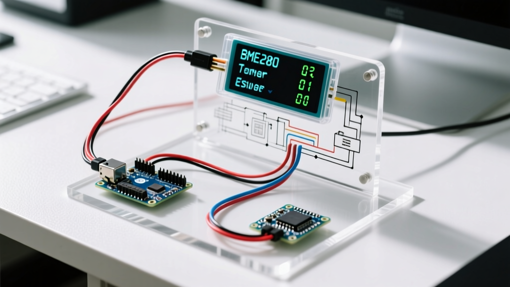
Integrating an arduino transparent display into a sensor project transforms a standard data logger into an augmented reality (AR) heads-up display (HUD). Unlike traditional screens that rely on a backlight blocking the view behind the panel, transparent displays allow ambient light to pass through the substrate. When pixels are unlit, the screen acts as tinted glass; when lit, the pixels emit light that appears to float over the background.
For microcontroller projects, transparent OLEDs (Organic Light-Emitting Diodes) are vastly superior to transparent TFT LCDs. TFTs require a complex backlight diffusion layer that reduces transparency to roughly 10-15%. Transparent OLEDs, utilizing a semi-transparent magnesium-silver (Mg:Ag) cathode and indium tin oxide (ITO) anode, achieve up to 40-60% optical transmission. This makes them ideal for overlaying real-time environmental telemetry onto physical environments, such as greenhouse monitoring panels or custom automotive gauges.
Component Selection & 2026 Pricing Matrix
Selecting the right transparent panel depends on your resolution requirements, interface bandwidth, and budget. Below is a comparison of the most reliable transparent displays available for Arduino integration in 2026.
| Display Model | Driver IC | Resolution | Interface | Approx. Price (2026) | Best Use Case |
|---|---|---|---|---|---|
| Seeed Studio 1.12" Transparent OLED | SSD1309 | 128 x 64 | I2C / SPI | $28.50 | Compact sensor HUDs, wearables |
| WiseChip 0.96" Transparent OLED | SSD1306 | 128 x 64 | SPI | $22.00 | High-speed SPI data streaming |
| Crystalfontz 2.1" Transparent TFT | ILI9341 | 240 x 320 | SPI | $47.00 | Complex UI, color overlays |
Note: For this tutorial, we will use the Seeed Studio 1.12" Transparent OLED (SSD1309) paired with a Bosch BME280 environmental sensor to build an I2C-based HUD.
Hardware Integration: Wiring the HUD Stack
The most common point of failure when wiring an arduino transparent display is ignoring logic level thresholds. Most modern transparent OLEDs and the Bosch BME280 sensor operate strictly at 3.3V logic. If you are using a 5V Arduino (like the Uno R3 or Nano), feeding 5V into the I2C SDA/SCL lines will degrade the display's internal I/O buffers over time, leading to I2C bus lockups.
Step-by-Step Wiring Guide
- Power Rails: Connect the Arduino 3.3V output to the breadboard's positive rail, and GND to the negative rail. Warning: The Arduino Nano's onboard 3.3V regulator is only rated for ~150mA. The OLED and BME280 combined draw roughly 45mA peak, which is within safe limits.
- Logic Level Shifting: Place a BSS138 bidirectional logic level converter on the breadboard. Connect the LV (Low Voltage) side to 3.3V and the HV (High Voltage) side to 5V.
- I2C Routing: Route the Arduino's A4 (SDA) and A5 (SCL) through the HV channels of the level shifter. Connect the LV channels to the shared I2C bus for both the BME280 and the Transparent OLED.
- Pull-up Resistors: Transparent displays often lack onboard I2C pull-up resistors to save space. Solder or wire 4.7kΩ pull-up resistors from the 3.3V LV I2C lines to the SDA and SCL pins.
Managing I2C Bus Capacitance and Address Collisions
When sharing an I2C bus between a sensor and a display, bus capacitance becomes a critical factor. The BME280 default I2C address is 0x76 (or 0x77), while the SSD1309 OLED typically sits at 0x3C. Because the addresses do not collide, communication conflicts are rare. However, long ribbon cables increase parasitic capacitance, which degrades the square wave edges of the I2C clock signal.
Pro-Tip: Keep I2C trace lengths under 15cm when using transparent OLEDs. If your HUD requires the screen to be mounted further away from the microcontroller, switch to an SPI interface or use an I2C bus extender like the PCA9600 to drive the capacitive load over longer distances.
Software Architecture: Rendering Sensor Data on Glass
Rendering on a transparent screen requires a paradigm shift: black is transparent, white is opaque. You cannot use dark backgrounds with light text, as drawing a black rectangle simply makes that area of the glass clear, rendering the text invisible against complex backgrounds. You must draw white text directly onto the 'empty' buffer.
We utilize the U8g2 library by Oliver Kraus, which offers superior font rendering and memory management compared to older Adafruit GFX forks for monochrome screens.
Initialization and Rendering Loop
For the Arduino Nano Every (which features 6KB SRAM), we can use the full buffer (F) constructor to prevent screen flickering during sensor updates. Standard Nanos (2KB SRAM) must use the paged (1) constructor.
#include <U8g2lib.h>
#include <Wire.h>
#include <Adafruit_BME280.h>

// Full buffer constructor for SSD1309 128x64 via HW I2C
U8G2_SSD1309_128X64_NONAME2_F_HW_I2C u8g2(U8G2_R0, U8X8_PIN_NONE);
Adafruit_BME280 bme;

void setup() {
  Wire.begin();
  u8g2.begin();
  bme.begin(0x76); // Default I2C address
}

void loop() {
  float temp = bme.readTemperature();
  float hum = bme.readHumidity();

  u8g2.clearBuffer();
  u8g2.setFont(u8g2_font_ncenB08_tr);

  // Draw floating text (White = Opaque, Black = Transparent)
  u8g2.drawStr(0, 15, "ENVIRONMENT HUD");
  u8g2.drawHLine(0, 20, 128); // Thin separator line

  u8g2.setFont(u8g2_font_logisoso16_tr);
  u8g2.setCursor(0, 45);
  u8g2.print(temp, 1);
  u8g2.print("C");

  u8g2.setCursor(70, 45);
  u8g2.print(hum, 0);
  u8g2.print("%");

  u8g2.sendBuffer();
  delay(2000); // BME280 sampling interval
}
Critical Failure Modes & Optical Troubleshooting
Building a HUD with an arduino transparent display introduces unique optical and electrical challenges not found in standard LCD projects. Refer to Adafruit's comprehensive OLED guide for baseline electrical troubleshooting, but keep these transparent-specific failure modes in mind:
- Ambient Light Washout: Because transparent OLEDs lack a backlight, their contrast ratio is entirely dependent on the environment. In direct sunlight, the white pixels (typically 150-200 cd/m² brightness) will wash out. Solution: Apply a polarizing film or a neutral density (ND) filter to the viewing side of the glass to improve perceived contrast in high-lumen environments.
- Differential Aging (Burn-in): OLED phosphors degrade with use. If your HUD displays static text (like the 'ENVIRONMENT HUD' header) 24/7, those specific pixels will dim faster than the rest of the glass, creating a permanent 'ghost' image. Solution: Implement a pixel-shifting algorithm in your code that moves the entire UI bounding box by 1-2 pixels in a circular pattern every 60 seconds.
- Moire Interference Patterns: When viewing the transparent display against a background with fine repeating patterns (like a mesh screen or louvers), the pixel grid of the OLED can create distracting moire interference. Solution: Tilt the display mounting bracket by 3 to 5 degrees off the vertical axis relative to the background pattern to break up the spatial frequency alignment.
Final Calibration Notes
When deploying your transparent sensor HUD in the field, ensure the BME280 is thermally isolated from the Arduino's voltage regulator. The heat generated by a 5V-to-3.3V linear regulator can skew the BME280's temperature readings by up to 2.5°C if mounted on the same PCB without thermal relief slots. By treating the transparent display not just as an output device, but as an optical combiner, you elevate a basic Arduino sensor project into a professional-grade augmented reality interface.