
Choosing the Right Light Sensor for Arduino in 2026
Interfacing a light sensor for Arduino is one of the most fundamental skills in embedded systems design. Whether you are building an automated greenhouse lighting system, a smart home lux-triggered blind controller, or a simple dawn-simulating alarm clock, accurate ambient light measurement is critical. In 2026, hobbyists and engineers generally choose between two distinct paths: the traditional analog Photoresistor (LDR) and the modern digital I2C Lux Sensor (like the BH1750FVI).
This beginner-friendly tutorial goes beyond basic wiring diagrams. We will explore the exact voltage divider mathematics required for analog sensors, the I2C addressing nuances of digital modules, and the real-world failure modes that often trap novices. By the end of this guide, you will have production-ready code and a deep understanding of optical sensor integration.
Component Selection Matrix: Analog LDR vs. Digital I2C
Before writing a single line of code, you must select the correct hardware for your environmental constraints. Below is a technical comparison of the two most common light sensors for Arduino projects.
| Feature | GL5528 Analog LDR (Photoresistor) | BH1750FVI Digital I2C Module |
|---|---|---|
| Output Type | Analog Voltage (requires ADC) | Digital I2C (Lux value) |
| Measurement Range | Relative (0-1023 ADC), non-linear | Absolute (1 to 65,535 Lux), linear |
| Spectral Peak | 540nm (Green/Yellow light) | 550nm (Matches human eye response) |
| Response Time | Slow (20ms - 50ms) | Fast (Configurable, typically 120ms for high-res) |
| Typical Cost (2026) | $0.10 - $0.30 per unit | $1.50 - $2.50 per module |
| Best Use Case | Simple day/night detection, cost-sensitive builds | Precise lux monitoring, plant growth, smart home |
Deep Dive 1: Wiring and Coding the Analog LDR (GL5528)
The GL5528 is a cadmium sulfide (CdS) photoresistor. Its resistance drops as photon density increases. In total darkness, its resistance can exceed 1MΩ, while under bright direct sunlight (approx. 100,000 lux), it drops to roughly 5kΩ. Because the Arduino cannot read resistance directly, we must convert this resistance change into a voltage change using a voltage divider circuit.
The Voltage Divider Mathematics
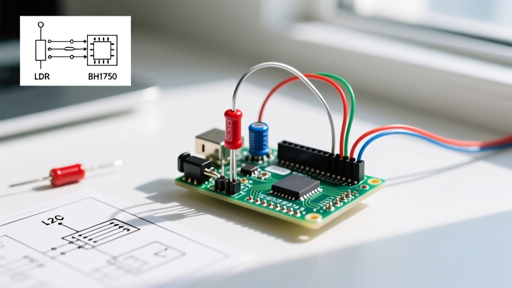
To interface the LDR with an Arduino Uno R3 or Nano, wire the circuit as follows:
- Connect a 10kΩ fixed resistor between the Arduino 5V pin and Analog Pin A0.
- Connect the LDR between Analog Pin A0 and GND.
The formula for the voltage at A0 is: V_out = 5V × (R_LDR / (R_Fixed + R_LDR))
Let us look at the exact ADC values (0-1023) you can expect based on this specific 10kΩ pull-up configuration:
- Bright Sunlight (R_LDR ≈ 5kΩ): V_out = 1.66V → ADC reads ~340
- Office Room Light (R_LDR ≈ 10kΩ): V_out = 2.50V → ADC reads ~511
- Complete Darkness (R_LDR ≈ 200kΩ): V_out = 4.76V → ADC reads ~975
Expert Insight: Notice that the relationship is highly non-linear. An LDR is excellent for determining if a room is "dark" or "bright," but it is mathematically cumbersome to use for calculating exact lux without complex logarithmic curve-fitting.
Arduino Code for LDR Interfacing
According to the official Arduino AnalogInOutSerial documentation, reading the pin is straightforward, but applying a software low-pass filter is crucial to eliminate 50Hz/60Hz mains hum interference picked up by the high-impedance analog node.
const int ldrPin = A0;
float smoothedValue = 0;
const float alpha = 0.1; // Filter weight
void setup() {
Serial.begin(115200);
}
void loop() {
int rawADC = analogRead(ldrPin);
smoothedValue = (alpha * rawADC) + ((1.0 - alpha) * smoothedValue);
Serial.print("Filtered ADC: ");
Serial.println(smoothedValue);
delay(50);
}
Deep Dive 2: Wiring and Coding the Digital BH1750FVI
For applications requiring precise, human-eye-calibrated lux measurements, the BH1750FVI is the undisputed industry standard for hobbyists. It communicates via I2C and outputs a calibrated 16-bit digital value, completely bypassing the need for ADC calibration or voltage divider math.
I2C Wiring and the 3.3V vs 5V Trap
The BH1750 chip itself operates strictly between 2.4V and 3.6V. Critical Failure Mode: If you buy a bare-bones breakout board without an onboard voltage regulator and connect it to an Arduino Uno's 5V pin, you will instantly destroy the silicon. However, most modules sold in 2026 (like those from Adafruit or generic Amazon clones) include a 3.3V LDO (Low Dropout Regulator) and I2C level shifters, making them 5V tolerant. Always check your module's schematic.
Wire the module as follows:
- VCC: 5V (if module has LDO) or 3.3V (if bare chip)
- GND: GND
- SCL: A5 (on Uno/Nano) or dedicated SCL pin
- SDA: A4 (on Uno/Nano) or dedicated SDA pin
- ADDR: Leave floating or tie to GND for default I2C address
0x23. Tie to VCC to change address to0x5C.
Arduino Code for BH1750 I2C Integration
We will use the native Arduino Wire Library to communicate with the sensor. This avoids third-party library bloat and teaches you direct I2C register manipulation.
#include <Wire.h>
#define BH1750_ADDRESS 0x23
#define BH1750_CONTINUOUS_HIGH_RES_MODE 0x10
void setup() {
Wire.begin();
Serial.begin(115200);
// Initialize the sensor in continuous high-res mode (1 lux resolution)
Wire.beginTransmission(BH1750_ADDRESS);
Wire.write(BH1750_CONTINUOUS_HIGH_RES_MODE);
Wire.endTransmission();
}
void loop() {
Wire.requestFrom(BH1750_ADDRESS, 2);
if (Wire.available() == 2) {
uint16_t rawLux = Wire.read() << 8;
rawLux |= Wire.read();
float lux = rawLux / 1.2; // Datasheet correction factor
Serial.print("Ambient Light: ");
Serial.print(lux);
Serial.println(" lx");
}
delay(250); // High-res mode takes ~180ms per measurement
}
Real-World Troubleshooting and Edge Cases
Even with perfect wiring, environmental and electrical factors can cause erratic sensor behavior. Here is how to diagnose the most common issues encountered in the field.
1. I2C Bus Lockups (BH1750)
If your Arduino freezes or the BH1750 stops responding, the I2C bus has likely locked up. This happens if the Arduino resets exactly while the sensor is pulling the SDA line LOW. According to the NXP I2C-bus specification and user manual, the master must toggle the SCL clock line 9 times to force the slave to release the SDA line. If you are building a commercial product, implement a software I2C bus recovery routine in your setup() function before calling Wire.begin().
2. LDR Thermal Drift and Hysteresis
CdS photoresistors suffer from thermal drift. If your LDR is placed near a heat source (like a voltage regulator or an enclosed outdoor weatherproof box in direct sun), its dark resistance will drop, causing the Arduino to falsely read that the environment is brighter than it actually is. Furthermore, LDRs exhibit a "memory effect" (hysteresis) where exposure to extreme light temporarily alters their baseline resistance. For outdoor weather stations, always use a digital BH1750 housed in a PTFE diffusion dome to mitigate thermal and directional errors.
3. Missing I2C Pull-Up Resistors
While many BH1750 breakout boards include 4.7kΩ pull-up resistors on the SDA and SCL lines, some ultra-cheap clones omit them to save $0.02 in manufacturing. If your I2C scanner finds no devices, use a multimeter to check for continuity between SDA/SCL and VCC. If absent, solder two 4.7kΩ resistors from the data lines to the 3.3V/5V rail to stabilize the bus capacitance.
Conclusion
Selecting and wiring a light sensor for Arduino ultimately depends on your required precision. For simple, low-cost triggers where relative darkness is the only metric, the GL5528 LDR paired with a 10kΩ voltage divider remains a viable, penny-saving solution. However, for any 2026 IoT project requiring accurate, repeatable lux data for plant growth algorithms or smart home circadian lighting, the BH1750FVI digital module is the superior choice. By understanding the underlying mathematics and I2C protocols detailed above, you can bypass common beginner pitfalls and build robust, production-ready optical sensing circuits.