
The Anatomy of a Blank LCD Screen Arduino Failure
Despite the aggressive price drops of SSD1306 OLED modules in 2026, the classic 16x2 and 20x4 character LCD remains a sub-$3 staple for industrial-style readouts, retro gaming interfaces, and heavy-duty appliance diagnostics. Whether you are using a genuine Adafruit 181, a DFRobot DFR0063, or a generic QC1602A clone, the underlying controller is almost always a Hitachi HD44780 or a modern silicon equivalent like the Sunplus SPLC780D.
However, getting a blank, garbled, or single-row-block display is a universal rite of passage. A blank screen rarely means dead hardware; it usually points to a specific electrical mismatch or a legacy software conflict. This troubleshooting guide bypasses generic advice and provides exact multimeter measurements, I2C address matrices, and modern library solutions to get your LCD screen Arduino project running.
Step 1: The Contrast Voltage (V0) Trap
The most common cause of a 'blank' display that actually has a functioning backlight is an incorrect voltage on the V0 (Contrast) pin. Many outdated tutorials simply instruct you to 'connect a 10k potentiometer and turn it until you see text.' Let us look at the actual electrical requirements.
The Liquid Crystal Alignment Threshold
The LCD requires a specific voltage differential between VDD (Logic Power, typically 5V) and V0 to align the liquid crystals. Specifically, VDD - V0 must be between 4.5V and 5.0V for the pixels to become fully opaque (dark text on a light background).
- If VDD is 5.0V: Your V0 pin must sit between 0.0V and 0.5V.
- If V0 is left floating: The internal impedance pulls it high, resulting in a completely blank, bright green/blue screen.
- If V0 is exactly 2.5V: You will see nothing.
- If V0 is driven below 0V (negative): You will see solid black blocks across the entire row, indicating the contrast is maxed out.
Hardware Fix: If you are using an I2C backpack, locate the tiny blue trim potentiometer on the back of the PCB. Use a jeweler's screwdriver to turn it counter-clockwise while the Arduino is powered. If you are wiring a parallel display, do not rely on a voltage divider; use a dedicated 10k linear pot with the wiper tied to V0, one leg to GND, and the other to 5V.
Step 2: I2C Backpack Address Conflicts (PCF8574 vs. PCF8574A)
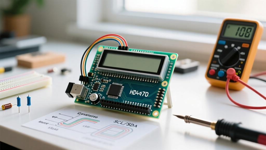
When transitioning from 16-wire parallel mode to 4-wire I2C, you are using an I/O expander chip soldered to the back of the LCD. The two most common chips are the NXP PCF8574T and the PCF8574AT. They look identical but have hard-coded, different base I2C addresses.
Identifying Your Expander Chip
- PCF8574T (or PCF8574): Base address is 0x27. (With A0, A1, A2 pads open).
- PCF8574AT: Base address is 0x3F. (With A0, A1, A2 pads open).
If your Arduino sketch is hardcoded to LiquidCrystal_I2C lcd(0x27, 16, 2); but your board features the 'AT' variant, the microcontroller will send data into the void, resulting in a blank screen. You can verify the exact address by running an I2C Scanner sketch via the Arduino IDE Serial Monitor.
Expert Insight: According to the NXP PCF8574 I/O Expander Datasheet, the I2C bus requires pull-up resistors to function reliably. While most I2C LCD backpacks include 4.7kΩ pull-up resistors on the SDA and SCL lines, if you are daisy-chaining more than three I2C devices, the cumulative capacitance can degrade the signal edges. In 2026, if your I2C LCD randomly drops out or freezes, check your pull-up resistance with a multimeter; you may need to drop to 2.2kΩ resistors for high-speed bus stability.
Step 3: Library Mismatches and the Modern hd44780 Diagnostic
The legacy LiquidCrystal_I2C library by Frank de Brabander has been the default recommendation on forums for a decade. However, it suffers from a fatal flaw: it assumes a specific pin mapping between the PCF8574 expander and the LCD controller. Chinese manufacturers frequently alter this mapping to optimize PCB routing. If the library assumes D4 is on P0, but your board routes D4 to P4, the display will show garbled characters or remain completely blank.
The 2026 Standard: Auto-Detection
Stop guessing pin mappings. The definitive solution is the duinoWitchcraft hd44780 Repository maintained by Bill Perry. This library includes a built-in diagnostic tool that solves 90% of software-related blank screens.
- Install the
hd44780library via the Arduino IDE Library Manager. - Navigate to File > Examples > hd44780 > ioClass > hd44780_I2Cexp > I2CexpDiag.
- Upload and open the Serial Monitor at 9600 baud.
This sketch will actively scan the I2C bus, identify the exact address, deduce the internal PCF8574-to-HD44780 pin mapping automatically, and test the LCD memory. If the hardware is functional, it will print the exact constructor line you need to copy into your final sketch.
Hardware Troubleshooting Matrix
Use this diagnostic matrix to isolate the failure mode based on visual symptoms and multimeter readings.
| Visual Symptom | Probable Fault | Multimeter Test / Exact Solution |
|---|---|---|
| Solid Black Blocks (Top Row or All Rows) | Contrast voltage (V0) is too low (near 0V or negative). | Measure V0 to GND. Adjust trim pot until V0 reads ~0.4V. |
| Completely Blank (No Backlight) | Backlight circuit open, or missing current limiting resistor. | Check continuity on pins 15 (A) and 16 (K). Ensure 5V is reaching Pin 15. Check for a blown jumper wire. |
| Backlight ON, Screen Blank (No Blocks) | V0 floating, or logic voltage (VDD) below 4.5V. | Measure VDD (Pin 2). If <4.5V, fix power supply. Measure V0; tie to GND via 1k resistor to force blocks. |
| Single Row of Black Blocks | LCD controller failed to initialize, or RW pin floating. | Tie RW (Pin 5) directly to GND. Verify E (Pin 6) is receiving pulses via oscilloscope or logic probe. |
| Garbled / Custom Characters | I2C Pin Mapping mismatch, or data line noise. | Run I2CexpDiag sketch. If parallel, ensure 4-bit mode uses D4-D7 (Pins 11-14), not D0-D3. |
Power Supply Edge Cases: USB Brownouts and Backfeeding
A frequently overlooked cause of intermittent LCD screen Arduino failures is power supply sag. A standard 16x2 LCD with an LED backlight draws between 50mA and 120mA, depending on the color and series resistor. When combined with an Arduino Nano or Uno drawing 40mA, and a few sensors, your total 5V rail current can easily exceed 200mA.
The AMS1117-5.0 Bottleneck
If you are powering your project via the Arduino's USB port or barrel jack, the onboard linear voltage regulator (often a cheap AMS1117-5.0 clone) must dissipate significant heat. As the regulator heats up, its output voltage can sag from 5.0V down to 4.2V. The Arduino LiquidCrystal Official Documentation assumes a stable 5V logic level. When VDD drops below 4.5V, the HD44780 internal memory initialization fails silently, leaving the screen blank despite the backlight remaining on.
Fix: Bypass the Arduino's onboard regulator. Use a dedicated 5V buck converter (like an LM2596 module) to power the LCD's VDD and Backlight Anode directly from your main 9V/12V supply, sharing a common ground with the Arduino.
4-Bit Parallel Wiring Verification
If you are not using an I2C backpack and are wiring the LCD in 4-bit parallel mode, the margin for error is razor-thin. The most catastrophic mistake is leaving the RW (Read/Write) pin floating.
- RS (Register Select): Digital Pin (e.g., D12). Selects Command vs. Data register.
- RW (Read/Write): MUST BE TIED TO GND. If left unconnected, it acts as an antenna, picking up EMI and randomly forcing the LCD into 'Read' mode, locking the bus.
- E (Enable): Digital Pin (e.g., D11). Latches data into the controller on the falling edge.
- D4 to D7: Digital Pins (e.g., D5, D4, D3, D2). Note that the
LiquidCrystallibrary expects these in reverse order in the constructor compared to physical pin numbering.
Always verify your constructor matches your physical wiring exactly: LiquidCrystal lcd(RS, E, D4, D5, D6, D7);. By methodically checking the V0 threshold, confirming the PCF8574 I2C address, and migrating to the auto-detecting hd44780 library, you will eliminate blank display errors permanently from your prototyping workflow.