
The Challenge: Why BLDCs Require More Than Just Pins
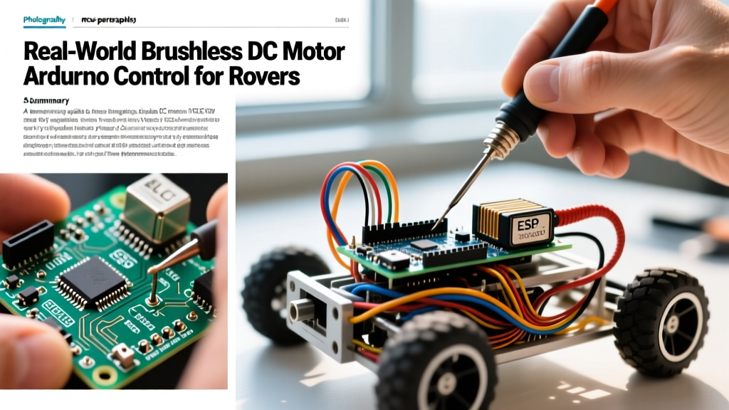
Building an autonomous agricultural rover or a heavy-duty inspection robot requires reliable, high-torque traction. While brushed DC motors are easy to wire, a brushless dc motor arduino setup provides the torque density, thermal efficiency, and lifespan required for continuous real-world operation. However, unlike a simple brushed motor where you apply voltage to the terminals, a Brushless DC (BLDC) motor requires precise electronic commutation to sequence the stator electromagnets and keep the rotor spinning.
In 2026, the DIY robotics community generally splits into two camps for BLDC control: the budget-friendly PWM/ESC method using standard RC car parts, and the professional closed-loop UART method using advanced FOC (Field Oriented Control) drivers. This guide breaks down both architectures, providing the exact wiring, code logic, and hardware specifications needed to integrate a BLDC motor into your next Arduino-based rover.
Hardware Bill of Materials (BOM) & Cost Breakdown
For a mid-sized rover (approx. 20kg payload capacity), a 190KV outrunner motor paired with a 6S LiPo battery is the industry sweet spot. Below is the verified BOM with current 2026 market pricing.
| Component | Model / Specification | Role | Est. Cost (USD) |
|---|---|---|---|
| Microcontroller | Arduino Nano 33 IoT | Logic & UART/PWM Generation | $26.00 |
| BLDC Motor | Turnigy SK3 6374 190KV | Traction Drive (High Torque) | $95.00 |
| Budget ESC | Hobbywing Skywalker 60A | Trapezoidal Commutation (PWM) | $38.00 |
| Pro Controller | Flipsky VESC 6.6 | FOC Commutation (UART/CAN) | $115.00 |
| Power Supply | Zippy Compact 6S 5000mAh | 22.2V Nominal Traction Power | $65.00 |
| Logic Power | Hobbywing 5V/3A UBEC | Isolated Arduino Power | $12.00 |
Method 1: The Budget PWM Approach (ESC + Servo Library)
The most common entry point for a brushless dc motor arduino project is repurposing a standard RC Electronic Speed Controller (ESC). The ESC handles the complex back-EMF sensing and trapezoidal commutation, while the Arduino simply sends a 50Hz PWM signal to dictate throttle position.
Wiring the ESC to the Arduino Nano
- Battery (B+ / B-): Connect directly to the 6S LiPo via an XT90 anti-spark connector.
- Motor Phases (A, B, C): Connect to the three BLDC motor wires. Order doesn't matter initially; swapping any two wires reverses the direction.
- Signal Wire (White/Yellow): Connect to Arduino Pin D9 (a hardware PWM capable pin).
- Ground (Black): Must be connected to the Arduino GND to establish a common logic reference.
- 5V BEC Wire (Red): Cut or isolate this wire. Do not use the ESC's internal linear BEC to power an Arduino loaded with sensors (like LiDAR or GPS). It will overheat and cause a brownout.
The Critical Arming Sequence
ESCs are designed for RC transmitters, which output a pulse width between 1000µs (0% throttle) and 2000µs (100% throttle). For safety, an ESC will refuse to arm if it detects a throttle signal upon power-up. You must send a 1000µs pulse for at least 2 seconds before the ESC will accept drive commands.
Expert Warning: If your Arduino boots and immediately sends a 1500µs (neutral) or higher pulse, the ESC will enter an error state, emit a continuous high-pitched beep, and lock out the motor. Always hardcode an arming delay in your setup() loop.
#include <Servo.h>

Servo roverESC;

void setup() {
  // Attach ESC to Pin 9, defining min/max pulse widths
  roverESC.attach(9, 1000, 2000);

  // Send 0% throttle (1000us) to initiate arming
  roverESC.writeMicroseconds(1000);

  // Wait for ESC to read the signal and arm (listen for the confirmation beep)
  delay(2500);
}

void loop() {
  // Example: Ramp up to 30% throttle (approx 1300us)
  roverESC.writeMicroseconds(1300);
  delay(3000);

  // Stop
  roverESC.writeMicroseconds(1000);
  delay(5000);
}
For deeper integration with standard Arduino timing, refer to the Arduino Servo Library Documentation, which details the hardware timer constraints on different microcontroller boards.
Method 2: The Pro Approach (VESC + UART Closed-Loop)
While PWM ESCs are cheap, they lack telemetry, precise low-speed torque control, and active braking. For a rover that needs to climb a 30-degree incline at exactly 0.5 meters per second without stalling, you need Field Oriented Control (FOC). The VESC Project Open Source Community has standardized the VESC 6.6 hardware, which interfaces beautifully with Arduino via UART.
Why UART Beats PWM in Real-World Rovers
- Telemetry Feedback: Over UART, the VESC sends real-time packets containing motor RPM, input voltage, current draw (Amps), and MOSFET temperature. Your Arduino can use this to implement thermal throttling.
- FOC Smoothness: FOC uses sine-wave commutation rather than the square-wave trapezoidal commutation of cheap ESCs. This eliminates the 'cogging' effect at low speeds, vital for precision camera rovers.
- No Arming Sequence: UART commands are discrete packets. There is no 2-second blind arming delay; the Arduino simply sends a 'Set Duty Cycle' or 'Set RPM' packet when ready.
Critical Failure Modes & Edge Cases
When deploying a brushless dc motor arduino system in the field, theoretical code often meets harsh physical realities. Anticipate these three specific failure modes:
1. Commutation Desync Under Load
The Symptom: The motor stutters violently, draws massive current spikes, and the ESC resets.
The Cause: In sensorless BLDC setups, the ESC relies on Back-EMF zero-crossing to time the commutation. If your rover hits a rock and the mechanical load spikes faster than the ESC's algorithm can track, it loses the rotor position.
The Fix: If using a VESC, enable the 'Hall Sensors' mode (requires wiring the motor's 5-pin hall sensor cable). If using a standard ESC, reduce the acceleration ramp in your code. Never jump from 1000µs to 1500µs instantly; ramp the PWM value in increments of 10µs per loop cycle.
2. EMI-Induced Runaway Throttle
The Symptom: The motor randomly accelerates to 100% without a command from the Arduino.
The Cause: The high-current switching of the ESC generates massive Electromagnetic Interference (EMI). If your PWM signal wire runs parallel to the motor phase wires, the EMI induces a voltage spike on the signal line, which the Arduino's Servo.h library misinterprets as a 2000µs pulse.
The Fix: Use twisted-pair wiring for the PWM and Ground signals. Keep signal wires at least 5cm away from the motor phase wires, and add a 10kΩ pull-down resistor between the PWM pin and GND on the Arduino to bleed off induced noise.
3. Logic Brownouts via Shared Ground
Even if you cut the 5V BEC wire from the ESC, the high-current ground return path can cause 'ground bounce.' When the motor pulls 40A, the voltage potential on the shared ground wire can temporarily rise by 1-2V, resetting the Arduino Nano. Always use a star-ground topology or an isolated DC-DC converter for the microcontroller's power supply.
Summary: Choosing Your Architecture
If you are building a lightweight, indoor prototype where cost is the primary constraint, the PWM ESC method paired with the Servo.h library remains a highly effective way to achieve a working brushless dc motor arduino integration. However, for outdoor, heavy-payload rovers operating in 2026's demanding DIY robotics landscape, investing the extra $75 in a VESC 6.6 and utilizing UART communication will save you hours of debugging desync issues and provide the telemetry required for truly autonomous navigation.