
The Physics of Acoustic Drift: Why Raw Code Fails
When prototyping with ultrasonic sensors, most developers rely on the basic pulseIn() example provided in standard tutorials. While sufficient for blinking an LED when an object approaches, this naive approach to Arduino sonar sensor code falls apart in real-world deployment. The primary culprit is acoustic drift caused by environmental variables.
Ultrasonic sensors calculate distance by measuring the time-of-flight (ToF) of a 40 kHz acoustic pulse. However, the speed of sound in air is not a static constant; it fluctuates primarily with temperature. According to thermodynamic principles documented by the Engineering Toolbox, the speed of sound in dry air increases by approximately 0.606 meters per second for every 1°C rise in temperature. If your code assumes a static speed of sound (typically 343 m/s at 20°C), a 15°C temperature swing between morning and afternoon will introduce a distance error of nearly 2.5%—translating to a 2.5 cm error at a 1-meter range.
Hardware Selection: Matching the Sensor to the Environment
Before optimizing your software, you must select hardware that aligns with your physical constraints. Blind zones, beam angles, and environmental sealing dictate your baseline accuracy.
| Sensor Model | Approx. Price (2026) | Blind Zone | Beam Angle | Best Use Case |
|---|---|---|---|---|
| HC-SR04 | $1.50 - $3.00 | 2 cm | ~30° | Indoor robotics, basic bin fill levels |
| JSN-SR04T (V2.0) | $8.00 - $12.00 | 20 cm | ~45° | Outdoor applications, waterproof enclosures |
| MaxBotix MB7389 | $65.00 - $75.00 | 30 cm | ~15° | Industrial tank gauging, high-precision mapping |
Note: The JSN-SR04T's 20 cm blind zone is a frequent point of failure for DIYers attempting to mount it flush inside a small chassis. Always account for the acoustic near-field dead zone.
Writing the Optimized Arduino Sonar Sensor Code
To achieve sub-millimeter reliability, your code must implement two critical layers of compensation: environmental adjustment and statistical jitter filtering. Relying on a single pulseIn() reading exposes your system to acoustic multipath interference and electrical noise.
Step 1: Environmental Compensation & Median Filtering
The following C++ implementation integrates a BME280 temperature sensor to dynamically adjust the speed of sound. It also utilizes a median filter rather than a simple moving average. A median filter is vastly superior for sonar data because it completely rejects 'ghost' echoes (outliers) caused by acoustic reflections off adjacent walls, whereas a moving average would skew the result toward the ghost reading.
#include <Wire.h>
#include <Adafruit_BME280.h>

Adafruit_BME280 bme;
const int trigPin = 9;
const int echoPin = 10;
const int sampleSize = 7; // Odd number for true median

float getSpeedOfSoundCmPerUs(float tempC) {
  // Base speed 331.3 m/s + 0.606 m/s per degree C
  // Converted to cm/uS: (331.3 + 0.606 * tempC) * 100 / 1000000
  return (331.3 + (0.606 * tempC)) * 0.0001;
}

float readMedianDistance() {
  float distances[sampleSize];
  float tempC = bme.readTemperature();
  float speed = getSpeedOfSoundCmPerUs(tempC);

  for (int i = 0; i < sampleSize; i++) {
    digitalWrite(trigPin, LOW);
    delayMicroseconds(5);
    digitalWrite(trigPin, HIGH);
    delayMicroseconds(10);
    digitalWrite(trigPin, LOW);

    // Timeout at 25000uS (~4.25 meters)
    long duration = pulseIn(echoPin, HIGH, 25000);
    distances[i] = (duration / 2.0) * speed;
    delay(20); // Acoustic settling time to prevent self-interference
  }

  // Simple insertion sort for median extraction
  for (int i = 1; i < sampleSize; i++) {
    float key = distances[i];
    int j = i - 1;
    while (j >= 0 && distances[j] > key) {
      distances[j + 1] = distances[j];
      j = j - 1;
    }
    distances[j + 1] = key;
  }
  return distances[sampleSize / 2];
}

void setup() {
  Serial.begin(115200);
  pinMode(trigPin, OUTPUT);
  pinMode(echoPin, INPUT);
  bme.begin(0x76);
}

void loop() {
  float preciseDistance = readMedianDistance();
  Serial.print("Calibrated Distance: ");
  Serial.print(preciseDistance, 2);
  Serial.println(" cm");
  delay(100);
}
Hardware-Level Calibration & Edge Cases
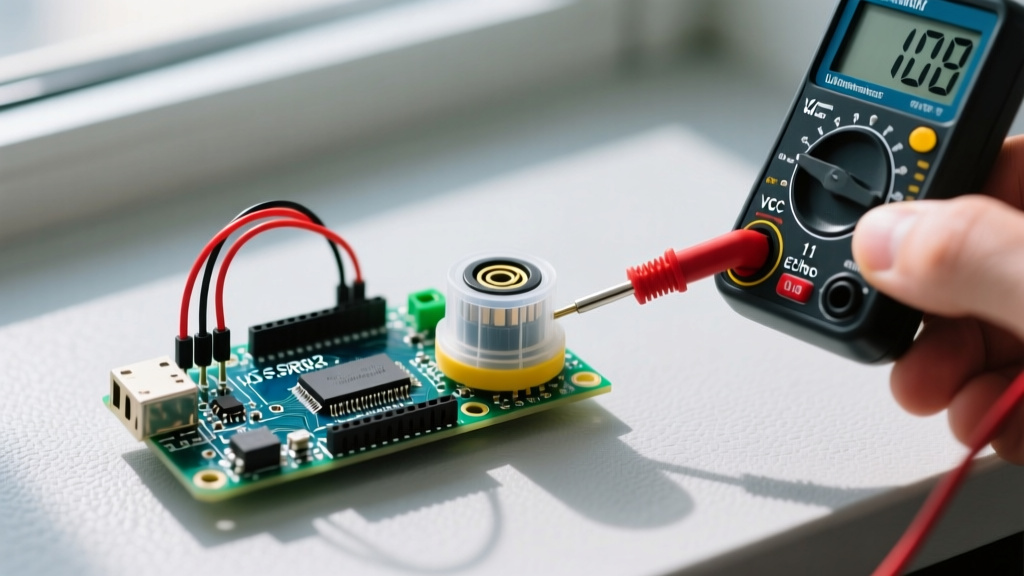
Even the most elegant Arduino sonar sensor code cannot compensate for poor electrical design. The HC-SR04 and JSN-SR04T are notorious for injecting high-frequency noise back into the 5V rail when their piezoelectric transducers fire. This noise can cause the microcontroller's internal timer to miscount the echo pulse width.
Power Decoupling Strategy
To stabilize the sensor's power delivery, you must implement a dual-capacitor decoupling network directly at the sensor's VCC and GND pins:
- 100µF Electrolytic Capacitor: Acts as a local energy reservoir to handle the sudden current spike (up to 30mA) when the transducer fires.
- 0.1µF Ceramic Capacitor: Placed in parallel, this shunts high-frequency switching noise away from the microcontroller's logic lines.
Acoustic Crosstalk in Multi-Sensor Arrays
If your robot uses four HC-SR04 sensors for 360° obstacle avoidance, firing them simultaneously will result in catastrophic crosstalk—Sensor A will read the echo from Sensor B's ping. The official Arduino Ping documentation warns against concurrent polling. You must implement a strict round-robin firing sequence in your code, enforcing a minimum 35-millisecond delay between pings to allow acoustic energy to dissipate below the sensor's noise floor.
Expert Troubleshooting Matrix
When your sensor outputs erratic data, use this diagnostic matrix to isolate the failure mode before rewriting your code.
| Symptom | Probable Cause | Hardware Fix | Software Fix |
|---|---|---|---|
| Readings occasionally spike to 400+ cm | Echo timeout / missed pulse | Check 5V rail sag; add decoupling caps | Ensure pulseIn() timeout is set; reject values > max range |
| Readings are consistently 5% too short | High ambient temperature | N/A | Implement dynamic temp compensation (see code above) |
| Random 0.00 cm readings | Target inside the blind zone | Reposition sensor physically backward | Clamp minimum output to sensor's spec blind zone |
| Slow, oscillating drift in static room | Acoustic multipath / standing waves | Add acoustic damping foam around transducer | Increase median filter window from 5 to 9 samples |
Summary: Moving Beyond the Prototype
Transitioning a sonar project from a breadboard prototype to a reliable field deployment requires treating sound as a physical medium, not just a digital signal. By integrating dynamic temperature compensation, deploying median filtering to reject ghost echoes, and stabilizing your hardware with proper decoupling capacitors, your Arduino sonar sensor code will deliver industrial-grade accuracy at a fraction of the cost. For further reading on advanced signal processing in ultrasonics, MaxBotix provides excellent application notes on environmental compensation and beam-shaping techniques that pair perfectly with the software strategies outlined above.