
The Reality of Raw Sensor Data
When you wire up a new distance sensor with Arduino, the raw readings rarely tell the whole truth. Whether you are building an autonomous rover, a liquid level monitor, or a precision 3D scanner, uncalibrated sensors will introduce drift, jitter, and systemic bias into your project. As of 2026, the market is flooded with highly capable ranging modules, but the physics of sound, light, and infrared triangulation still demand rigorous calibration to achieve millimeter-level accuracy.
This guide moves beyond basic ping() tutorials. We will explore the specific calibration methodologies for the three most dominant sensor architectures: Ultrasonic (HC-SR04/A02YYUW), Time-of-Flight (VL53L1X), and Infrared Analog (Sharp GP2Y0A21YK0F). By applying these hardware and software corrections, you can transform a $2 component into a precision instrument.
Ultrasonic Sensors: Temperature and Acoustic Compensation
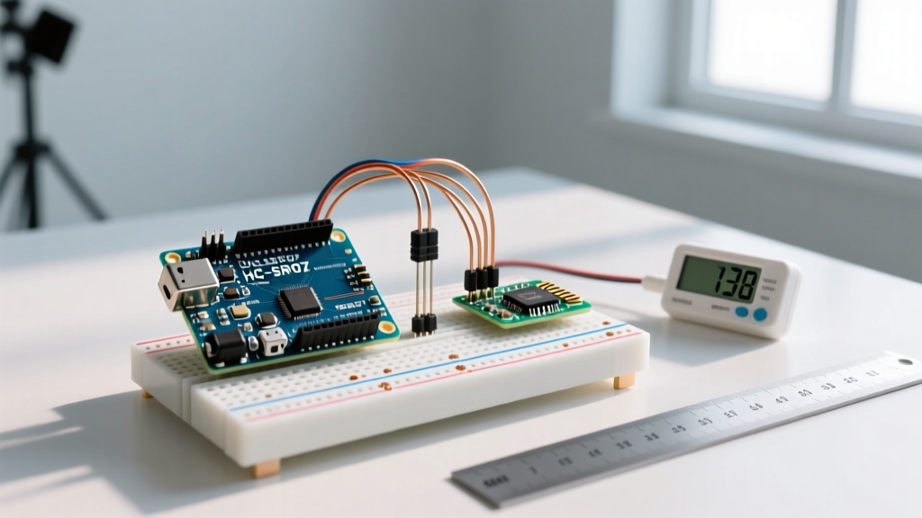
Ultrasonic sensors like the ubiquitous HC-SR04 (priced around $1.50 to $2.50) measure distance by timing the echo of a 40kHz acoustic pulse. The fundamental flaw in standard Arduino libraries is the assumption that the speed of sound is a constant 343 meters per second. In reality, the speed of sound in dry air is heavily dependent on ambient temperature.
The Physics of Acoustic Drift
According to The Engineering Toolbox, the speed of sound increases by approximately 0.606 m/s for every 1°C rise in temperature. If you calibrate your Arduino code for a 20°C room (343 m/s) but deploy the sensor in a 35°C greenhouse, your distance calculations will be off by nearly 2.5% over a 4-meter range—an error of 10 centimeters.
The Calibration Fix: Integrate a digital temperature sensor like the DS18B20 or BME280 into your I2C or OneWire bus. Update your distance formula dynamically in the Arduino loop:
Velocity (m/s) = 331.3 + (0.606 × Temperature in °C)
Distance (cm) = (Pulse Duration × Velocity) / 20000
Edge Case: Acoustic Shadowing and Beam Angle
Ultrasonic transducers emit a conical beam, typically around 30 degrees. If your target is angled or features sound-absorbing materials (like foam or heavy fabric), the acoustic wave will scatter, resulting in 'ghost' readings or timeouts. To mitigate this, implement a rolling median filter in your code rather than a simple moving average. A median filter of 5 samples will instantly discard the sporadic '0' or '4000' timeout values without skewing your baseline average.
Time-of-Flight (ToF): Offset and Crosstalk Calibration
The STMicroelectronics VL53L1X uses a 940nm VCSEL (Vertical-Cavity Surface-Emitting Laser) and a SPAD (Single Photon Avalanche Diode) array to measure the time it takes for photons to bounce back. While it boasts millimeter precision and costs between $7.00 and $9.00, it requires explicit field calibration to account for the protective cover glass and internal optical crosstalk.
Factory vs. Field Calibration
As noted in the official STMicroelectronics VL53L1X documentation, the sensor ships with factory calibration data stored in its NVM. However, the moment you place a piece of acrylic, glass, or a 3D-printed housing over the sensor aperture, the internal crosstalk changes. The cover glass reflects a fraction of the emitted laser directly back into the receiver, creating a false 'short distance' baseline.
Step-by-Step Offset Tuning
To calibrate the VL53L1X using the Pololu Arduino library, you must perform an offset calibration routine:
- Place a highly reflective target (like a white piece of paper or a Kodak gray card) at exactly 140mm from the sensor aperture.
- Ensure the environment is free of strong ambient 940nm infrared sources (direct sunlight will blind the SPAD array).
- Run the
sensor.calibrateOffset(140)function in your setup loop. - The library will fire multiple pulses, measure the internal crosstalk, and calculate the offset required to make the reading exactly 140mm.
- Save this offset value to the Arduino's EEPROM so you do not have to recalibrate on every boot.
Timing Budgets and Distance Modes
The accuracy of a ToF sensor is directly tied to its timing budget—the amount of time the sensor spends collecting photons. Adjusting this in your Arduino code allows you to balance speed versus precision.
| Distance Mode | Max Range (Dark) | Timing Budget | Accuracy / Precision | Best Use Case |
|---|---|---|---|---|
| Short | 1.3 meters | 20ms - 33ms | ± 2mm | Object avoidance, fast robotics |
| Medium | 3.0 meters | 33ms - 50ms | ± 4mm | Liquid level sensing, general ranging |
| Long | 4.0 meters | 50ms - 100ms | ± 8mm | Room mapping, slow-moving targets |
Infrared Analog: Polynomial Curve Fitting
The Sharp GP2Y0A21YK0F (10cm to 80cm range, approx. $5.00) relies on optical triangulation. An infrared LED projects a beam onto the target, and a Position Sensitive Detector (PSD) reads the angle of the reflected light. Because of the trigonometric nature of triangulation, the analog voltage output is highly non-linear. Attempting to use the Arduino map() function will yield massive inaccuracies.
The Hardware Prerequisite: Decoupling
Before writing a single line of calibration code, you must address the sensor's notorious power draw spikes. The SparkFun Sharp Distance Sensors Hookup Guide explicitly warns that the IR LED pulses cause severe voltage ripple. You must solder a 10µF to 47µF tantalum or electrolytic capacitor directly across the VCC and GND pins on the sensor itself. Without this, your Arduino's ADC will read chaotic, jittery values regardless of your software calibration.
Generating the Regression Formula
To calibrate the Sharp sensor, you must map the non-linear voltage curve:
- Mount the sensor on a rigid jig facing a flat, matte-white target.
- Move the target in 5cm increments from 10cm to 80cm.
- At each increment, record the raw analog read value (0-1023) or the converted voltage.
- Export this data to Excel, Python, or an online regression calculator.
- Generate a 3rd-order polynomial equation (e.g., y = ax³ + bx² + cx + d).
Implement this polynomial formula directly in your Arduino code. This mathematical curve fitting will linearize the output, giving you distance readings accurate to within ±1cm across the entire operational range.
Hardware-Level Accuracy Boosters
Software calibration cannot fix a compromised electrical signal. Implement these hardware best practices to ensure your Arduino receives clean data:
- Twisted Pair Wiring: For analog IR sensors, twist the signal wire with the ground wire to reject common-mode electromagnetic interference (EMI) from nearby stepper motors or relays.
- Dedicated Voltage Regulators: Ultrasonic and ToF sensors are sensitive to voltage drops. Power them via a dedicated 5V or 3.3V LDO regulator rather than sharing the Arduino's onboard 5V rail, which may sag when servos activate.
- I2C Pull-Up Resistors: The VL53L1X communicates via I2C. If your cable run exceeds 15cm, the internal pull-ups are insufficient. Add external 4.7kΩ pull-up resistors to the SDA and SCL lines to prevent data corruption and I2C bus lockups.
Troubleshooting Common Calibration Failures
Even with perfect math, environmental factors can break your calibration. Use this diagnostic matrix to identify the root cause of your ranging errors.
| Symptom | Likely Culprit | Corrective Action |
|---|---|---|
| Ultrasonic reads '0' or max distance randomly | Acoustic shadowing or 5V rail sag | Add a 100µF bulk capacitor on VCC; ensure target is perpendicular to the beam. |
| ToF reads exactly 20mm when uncovered | Cover glass crosstalk | Re-run calibrateOffset() with the final enclosure installed. |
| ToF fails to initialize on I2C | Missing pull-ups or wrong address | Verify 4.7kΩ pull-ups; ensure XSHUT pin is pulled HIGH to exit standby. |
| IR Analog output is wildly erratic | Missing decoupling capacitor | Solder a 10µF+ capacitor directly on the sensor's VCC/GND pins. |
| IR reads inaccurately on black objects | Low surface reflectivity | IR sensors require >18% reflectivity; switch to a ToF sensor for dark targets. |
Final Thoughts on Sensor Fusion
No single distance sensor with Arduino is perfect for every scenario. Ultrasonic sensors excel at detecting transparent objects like glass, ToF sensors provide pinpoint accuracy in tight spaces, and IR sensors offer a budget-friendly analog alternative. For mission-critical robotics in 2026, the ultimate calibration strategy is sensor fusion: combining a ToF sensor for precision with an ultrasonic sensor for wide-angle acoustic coverage, using a Kalman filter in your Arduino code to merge the datasets into a single, unshakeable ground truth.