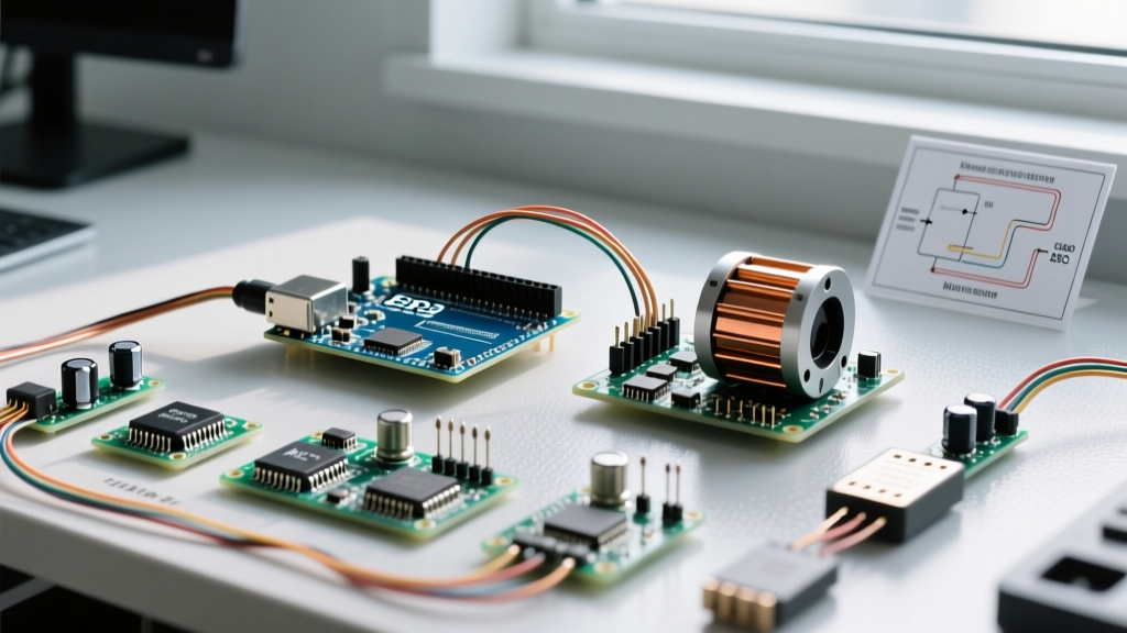

The Reality of Driving BLDC Motors with Microcontrollers
Brushless DC (BLDC) motors are the undisputed kings of modern electromechanical design, offering superior torque-to-weight ratios, high efficiency, and zero brush wear. However, interfacing a BLDC motor Arduino setup is not as simple as toggling a digital pin high. Unlike brushed DC motors, BLDC motors require precisely timed, high-current, three-phase alternating waveforms to commutate the stator coils. An Arduino's 5V logic and 40mA pin limits cannot drive these phases directly.
To bridge the gap between low-voltage logic and high-power 3-phase AC, you must use an Electronic Speed Controller (ESC) or a dedicated Field Oriented Control (FOC) driver board. More importantly, the hardware is only half the battle; selecting the correct software library dictates whether your motor spins with crude RC-car jerky motions or achieves smooth, high-precision servo-like control. In this comprehensive guide, we break down the best hardware drivers and software libraries for BLDC motor Arduino integration in 2026.
Hardware Matrix: Choosing the Right ESC or Driver
Before writing a single line of code, you must match your driver hardware to your application's torque, precision, and budget requirements. Below is a comparison of the three most common hardware paradigms for Arduino-based BLDC control.
| Hardware Type | Example Model (2026) | Avg. Price | Control Protocol | Best Use Case |
|---|---|---|---|---|
| Standard RC ESC (Sensorless) | Hobbywing Skywalker 40A | $25 - $35 | 50Hz PWM (1000-2000µs) | Drones, RC cars, basic propulsion |
| FOC Shield (Sensored/Sensorless) | STMicroelectronics B-G431B-ESC1 | $35 - $45 | I2C / SPI / UART | Robotics, gimbals, precision positioning |
| Industrial FOC Controller | ODrive Pro 24V | $180 - $220 | CAN bus / UART / Step-Dir | CNC machines, heavy automation, AGVs |
The Big Three: Arduino Libraries for BLDC Control
Once your hardware is selected, the software architecture must follow suit. Here is a deep dive into the three dominant libraries used in the Arduino ecosystem for BLDC commutation.
1. The Standard Servo.h Library (For RC ESCs)
If you are using a standard Hobbywing, Turnigy, or T-Motor RC ESC, the ESC internally handles the complex 3-phase trapezoidal commutation. It expects a standard 50Hz PWM signal, identical to what an RC receiver outputs to a servo. The built-in Arduino Servo Library Reference is all you need.
Critical Arming Sequence: RC ESCs feature a safety lockout. If you send a throttle command immediately upon boot, the ESC will reject it and beep an error tone. You must send a 1000µs (0% throttle) signal for at least 2 to 3 seconds during setup() to 'arm' the ESC before commanding motion.
Limitations: RC ESCs are optimized for high-RPM propellers, not low-speed torque. Attempting to run an RC ESC below 10% throttle often results in 'cogging' or complete desynchronization.
2. SimpleFOC (For Precision FOC Control)
Field Oriented Control (FOC) transforms the 3-phase AC motor into a mathematically decoupled DC motor, allowing for buttery-smooth low-speed torque and precise position holding. The SimpleFOC GitHub Repository is the gold standard for this on Arduino-compatible boards (specifically those with hardware PWM capabilities like the STM32 or Arduino Portenta).
SimpleFOC requires position feedback. While sensorless FOC exists, it struggles at zero speed. For robotics, pairing a B-G431B-ESC1 board with an AS5600 I2C magnetic encoder is the most cost-effective, high-precision setup available.
- Velocity Control: Maintains exact RPM regardless of load changes.
- Position Control: Acts like a high-torque servo motor with PID tuning.
- Torque Control: Uses current sensing to apply exact physical force (ideal for haptic feedback or compliant robotics).
3. ODrive Arduino Library (For High-Power Industrial setups)
When your BLDC motor draws upwards of 40A continuous and requires industrial-grade reliability (e.g., NEMA 34 BLDCs or hoverboard motors), the ODrive Pro is the premier choice. The ODrive Robotics Official Documentation outlines how to interface the ODrive via UART or CAN bus. Unlike SimpleFOC, which calculates FOC algorithms on the microcontroller, ODrive handles the heavy math on its own dedicated STM32 processor, leaving your Arduino free to handle high-level path planning and kinematics.
Step-by-Step: Wiring an AS5600 Encoder for SimpleFOC
To achieve closed-loop position control with SimpleFOC, you need an encoder. The AS5600 is a 12-bit magnetic rotary position sensor that communicates via I2C. Here is how to wire it to an Arduino Nano and a generic FOC shield:
- Power: Connect AS5600 VCC to the Arduino 5V (or 3.3V depending on your specific module breakout) and GND to GND.
- Data Lines: Connect SDA to Arduino A4 and SCL to A5.
- Magnet Mounting: Secure a 6x2.5mm neodymium radial magnet to the BLDC motor shaft. The air gap between the magnet and the AS5600 die must be exactly 2.0mm to 3.0mm for linear output.
- Pull-up Resistors: I2C lines are highly susceptible to the massive electromagnetic interference (EMI) generated by 3-phase PWM switching. Solder 4.7kΩ pull-up resistors directly at the AS5600 breakout board to prevent packet loss.
Power Architecture: Avoiding the BEC Brownout Trap
The most common point of failure in a BLDC motor Arduino project is not the code; it is the power delivery. Most RC ESCs and entry-level FOC shields include a BEC (Battery Eliminator Circuit) designed to power the microcontroller.
The Failure Mode: A typical BEC outputs 5V at 2A. However, when a BLDC motor experiences a sudden mechanical load, current spikes cause voltage ripple on the main battery bus. This ripple couples into the BEC, causing the 5V logic rail to momentarily sag to 4.2V or lower. The Arduino's ATmega328P or STM32 chip detects this as a brownout and instantly resets. Your motor goes limp, and your robot crashes.
The Professional Fix
Never rely on a high-current motor driver's internal BEC for sensitive logic. Instead, use an isolated DC-DC buck converter (such as an LM2596 module set to 5.2V) wired directly to the battery terminals to power the Arduino and sensors. Ensure the ground of the logic power supply and the motor power supply are tied together at a single star-ground point to prevent ground loops.
Troubleshooting Common Edge Cases
Even with perfect wiring, BLDC integration presents unique software-hardware edge cases. Keep this diagnostic matrix handy:
- Motor Stutters and Beeps Continuously: The ESC is not armed, or the PWM frequency is wrong. RC ESCs demand exactly 50Hz. If using
analogWrite()(which defaults to ~490Hz), the ESC will ignore the signal. You must use timer interrupts or theServo.hlibrary to enforce 50Hz. - SimpleFOC Motor Vibrates Violently at Standstill: Your PID derivative (D) gain is too high, or your encoder is experiencing EMI noise. Lower the D gain to zero, tune the Proportional (P) gain first, and check your I2C shielding.
- Motor Desyncs at High RPM: Sensorless ESCs track the motor's Back-EMF to determine rotor position. If you command an acceleration ramp that is too steep, the rotor falls behind the stator field, Back-EMF is lost, and the ESC desyncs. Implement a software acceleration limit (e.g.,
motor.acceleration_limit = 50;in SimpleFOC). - Overheating ESC at Low Speeds: Standard trapezoidal RC ESCs are horribly inefficient at low RPMs because they apply full battery voltage in rapid, low-duty-cycle pulses. If your application requires sustained low-speed, high-torque operation, you must abandon RC ESCs and migrate to an FOC driver like the B-G431B-ESC1.
Final Thoughts on BLDC Integration
Successfully driving a BLDC motor with an Arduino requires treating the system as a holistic mechatronic assembly rather than isolated components. By matching the correct ESC hardware to your mechanical requirements, selecting the appropriate library (Servo for simple propulsion, SimpleFOC for robotics, ODrive for heavy automation), and engineering a robust, isolated power delivery network, you can unlock the full, silent, and high-torque potential of brushless technology in your next DIY build.