
The Enduring Role of IR in Modern Microcontroller Projects
Even in 2026, with the proliferation of BLE and Wi-Fi modules, the IR sensor and Arduino combination remains a cornerstone of low-power, line-of-sight control systems. Whether you are building a retro-gaming console interface, a motorized camera slider, or a custom home automation remote, infrared communication offers unmatched simplicity and zero network overhead. However, the transition from legacy tutorials to modern driver architectures has left many makers struggling with deprecated library calls and hardware timer conflicts.
This comprehensive driver guide moves beyond basic blinking LEDs. We will dissect the hardware-level requirements of modern IR receiver diodes, navigate the architectural shifts in the IRremote v4.x library, and resolve the infamous AVR timer collisions that plague complex sketches.
Hardware Selection: Modules vs. Raw Photodiodes
Before writing a single line of driver code, you must select the right receiver hardware. The market is flooded with cheap modules, but understanding the silicon inside them is critical for signal integrity.
| Component | Type | Carrier Freq | Avg Price (2026) | Best Use Case |
|---|---|---|---|---|
| KY-022 Module | Integrated PCB | 38 kHz | $1.50 - $2.20 | Rapid prototyping, breadboards |
| Vishay TSOP38238 | Raw IC | 38 kHz | $0.85 - $1.10 | Custom PCBs, tight spaces, low noise |
| VS1838B | Raw IC (Generic) | 38 kHz | $0.15 - $0.30 | High-volume, low-cost consumer toys |
While the KY-022 is ubiquitous in starter kits, it often lacks adequate power supply filtering. For professional or permanent installations, we highly recommend the Vishay TSOP38238. Its internal pre-amplifier and automatic gain control (AGC) are specifically designed to suppress optical noise from compact fluorescent lamps (CFLs) and modern LED displays.
Crucial Wiring: The Decoupling Requirement
A common failure mode when pairing an IR sensor and Arduino is erratic decoding, often manifesting as random button presses or dropped frames. This is rarely a software bug; it is almost always power rail noise. The USB 5V rail on standard Arduino Unos and Nanos is notoriously noisy.
- VCC Pin: Connect to 5V through a 47Ω to 100Ω series resistor.
- Decoupling Capacitor: Place a 4.7µF to 10µF electrolytic capacitor directly across the VCC and GND pins of the TSOP38238.
- Data Pin: Connect directly to your chosen digital pin. The internal pull-up resistor of the ATmega328P (approx. 20kΩ-50kΩ) is sufficient; an external 10kΩ pull-up is optional but recommended for cable runs exceeding 30cm.
The IRremote v4.x Ecosystem: Breaking Changes & Setup
If you are following tutorials from 2019 or earlier, your code will not compile in the modern Arduino IDE. The Arduino-IRremote library underwent a massive architectural overhaul in version 3.0, which has been stabilized and expanded in the v4.x releases of 2025/2026.
Developer Note: The legacy
IRrecvclass and the.hheader file have been deprecated. Modern implementations require theIrReceiversingleton object and the.hppheader extension.
Modern Driver Implementation
Below is the bare-minimum, non-blocking receiver setup utilizing the modern API. This approach prevents the library from monopolizing the main loop, allowing your Arduino to handle display refreshes or motor controls concurrently.
#include <IRremote.hpp>

const uint8_t IR_RECEIVE_PIN = 2;

void setup() {
    Serial.begin(115200);
    // Initialize the receiver, enable LED feedback on pin 13 (optional)
    IrReceiver.begin(IR_RECEIVE_PIN, ENABLE_LED_FEEDBACK);
}

void loop() {
    if (IrReceiver.decode()) {
        // Print the protocol and decoded data
        Serial.println(IrReceiver.decodedIRData.protocol);
        Serial.println(IrReceiver.decodedIRData.decodedRawData, HEX);

        // Crucial: Resume receiving to clear the buffer
        IrReceiver.resume();
    }
}
Navigating Hardware Timer Conflicts
The most documented point of failure when integrating an IR sensor and Arduino is the hardware timer collision. Infrared decoding requires precise microsecond-level pulse measurement. To achieve this without blocking the CPU, the IRremote library utilizes the microcontroller's hardware timers.
On an ATmega328P (Arduino Uno/Nano), the library defaults to Timer2. If your sketch also uses the tone() function (which relies on Timer2) or certain PWM pins, the compiler will either throw an error, or the IR decoding will silently fail.
Resolution Strategies for AVR Boards
- Use an Alternative Timer: You can force the library to use Timer1 by defining a macro before including the library. Note that Timer1 is also used by the
Servo.hlibrary.#define IR_USE_AVR_TIMER1 #include <IRremote.hpp> - Pin Mapping Awareness: If you use Timer1 for IR, you lose hardware PWM on pins 9 and 10. If you use Timer2, you lose PWM on pins 3 and 11. Plan your motor driver or LED wiring accordingly.
The ESP32 Advantage in 2026
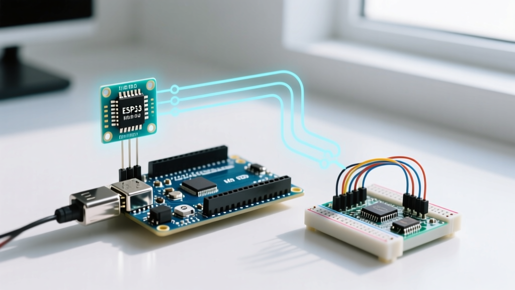
If your project requires simultaneous servo control, audio generation, and IR decoding, migrating to an ESP32 is the optimal hardware decision. The ESP32 port of the IRremote library utilizes the RMT (Remote Control Transceiver) peripheral. The RMT is a dedicated hardware block specifically designed for IR and LED strip protocols, completely bypassing the general-purpose CPU timers and eliminating all software-level collisions.
Advanced Protocol Decoding: Handling Repeat Frames
A frequent logic error in DIY remote control projects is mishandling 'Repeat' frames. When a user holds down a button on an NEC remote, the transmitter does not continuously send the full 32-bit command. Instead, it sends the command once, followed by a specific repeat code (usually 0xFFFFFFFF in legacy libraries, or a dedicated NEC repeat flag in v4.x).
To build a responsive UI—such as holding a button to increase volume or pan a camera—you must explicitly handle the REPEAT protocol flag provided by the modern driver.
if (IrReceiver.decode()) {
    if (IrReceiver.decodedIRData.flags & IRDATA_FLAGS_IS_REPEAT) {
        // Handle continuous press (e.g., keep motor running)
        Serial.println("Repeat detected - continuing action");
    } else {
        // Handle initial button press
        Serial.print("New Command: ");
        Serial.println(IrReceiver.decodedIRData.command, HEX);
    }
    IrReceiver.resume();
}
Troubleshooting Matrix: Driver & Hardware Failures
When your IR sensor and Arduino setup fails to register inputs, use this diagnostic matrix to isolate the fault domain.
| Symptom | Root Cause | Driver / Hardware Fix |
|---|---|---|
| Random, invalid hex codes generated without pressing remote | Optical noise or 5V rail ripple triggering AGC | Add 10µF decoupling cap; shield sensor from direct sunlight/CFLs. |
IRremote compiles, but decode() always returns false |
Hardware Timer collision (e.g., tone() active) |
Disable tone() or redefine IR timer via IR_USE_AVR_TIMER_X. |
| Remote works at 10cm, but fails at 2 meters | Carrier frequency mismatch (36kHz remote vs 38kHz sensor) | Verify remote carrier. Swap TSOP38238 for TSOP38236 if necessary. |
Compile Error: IRrecv does not name a type |
Using legacy v2.x code with modern v4.x library | Refactor to use IrReceiver.begin() and include <IRremote.hpp>. |
Summary and Best Practices
Successfully integrating an IR sensor and Arduino in modern development environments requires abandoning outdated tutorials and respecting the hardware's physical and architectural constraints. By utilizing the Vishay TSOP38238 with proper decoupling, adopting the non-blocking IrReceiver singleton in IRremote v4.x, and strategically managing AVR hardware timers, you can build robust, low-latency infrared control systems. For complex multitasking projects involving motors and audio, consider leveraging the ESP32's RMT peripheral to bypass timer limitations entirely.
For deeper technical specifications on microcontroller timer mapping and interrupt handling, refer to the official Arduino Language Reference.