
The Dual Challenge: Optical Contrast and Touch Matrix Accuracy
When integrating an Arduino and LCD screen into a precision measurement project, developers often focus entirely on the sensor code while neglecting the display's physical and electrical calibration. Whether you are building a digital multimeter, a weather station, or an industrial HMI (Human-Machine Interface), an uncalibrated display introduces two critical failure modes: optical misinterpretation due to poor contrast, and spatial inaccuracy due to uncalibrated touch matrices. This guide provides a deep-dive, hardware-level approach to calibrating both standard character LCDs and TFT resistive touch shields to ensure your data readouts are both visually legible and interactively precise.
Optical Calibration for I2C Character LCDs (HD44780 Controller)
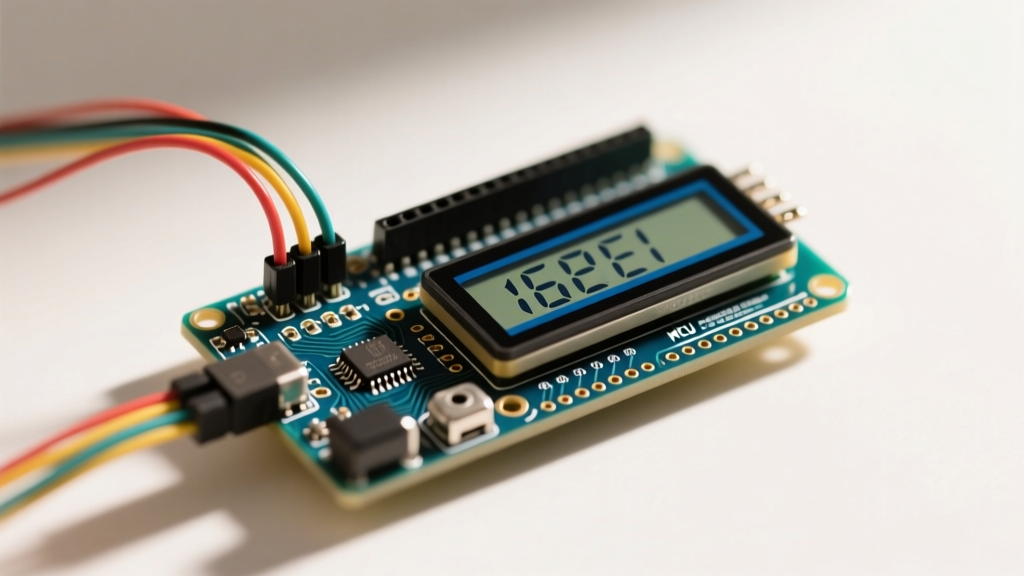
The ubiquitous 16x2 and 20x4 character LCDs, driven by the Hitachi HD44780 controller or its modern equivalents, remain a staple in DIY electronics. While they do not require software calibration, their optical accuracy—the ability of the human eye to correctly read segments under varying ambient light—relies entirely on precise voltage calibration at the hardware level.
Dialing in the V0 Contrast Voltage
Most I2C LCD backpacks (like those based on the PCF8574 expander chip operating at I2C address 0x27 or 0x3F) feature a small 10kΩ trimpot on the rear. This potentiometer adjusts the voltage fed to the V0 pin (Pin 3) of the LCD. According to the HD44780U Dot Matrix Liquid Crystal Display Controller/Driver Datasheet, the contrast is dictated by the voltage difference between VDD (5V) and V0. For optimal optical clarity at 25°C, the VDD-V0 differential should be precisely between 4.2V and 4.6V. This means the absolute voltage at the V0 pin must be calibrated to sit between 0.4V and 0.8V.
Pro-Tip: Do not adjust the trimpot by eye alone. Use a digital multimeter to probe the V0 pin while the backlight is active. Set your multimeter to DC voltage, ground the black probe, and touch the red probe to Pin 3. Dial the potentiometer until you hit exactly 0.55V for standard green/blue backlights.
Temperature Compensation for Outdoor Enclosures
Liquid crystals are highly sensitive to ambient temperature. If your Arduino and LCD screen are deployed in an outdoor enclosure where temperatures fluctuate from 0°C to 40°C, a static V0 voltage will cause the screen to wash out in the heat or turn completely black in the cold. Liquid crystals require a negative temperature coefficient for contrast voltage (roughly -0.03V/°C). To fix this, advanced builders bypass the standard 10kΩ trimpot and solder a 10kΩ NTC thermistor in series with a 4.7kΩ fixed resistor to create a temperature-compensating voltage divider. This hardware hack automatically drops the V0 voltage as the enclosure heats up, maintaining perfect optical accuracy without software intervention.
Resistive Touchscreen Matrix Calibration (TFT Shields)
When upgrading to a color TFT display, such as the Adafruit 2.8" TFT Touch Shield (Product ID 1651, approx. $34.95), the calibration challenge shifts from optical voltage to spatial coordinate mapping. Resistive touchscreens do not natively output pixel coordinates (e.g., X:120, Y:240). Instead, they output raw 10-bit ADC values (0-1023) that vary based on the specific resistance of the screen's ITO (Indium Tin Oxide) layers.
Extracting Raw ADC Boundaries
To calibrate the touch matrix, you must first determine the raw ADC boundaries of your specific screen. Using the Arduino TouchScreen.h library, you initialize the screen using the four analog/digital pins (XP, YP, XM, YM) and the specific X-plate resistance (typically 300Ω for Adafruit shields, but can range from 250Ω to 340Ω on generic Elecrow or DFRobot shields). By running a boundary test—pressing a stylus on the extreme top-left and bottom-right corners—you capture the raw minimum and maximum values. According to the Adafruit 2.8" TFT Touch Shield Guide, raw values are rarely a perfect 0 to 1023. They usually hover around 100 to 900 due to the physical bezel overlap and voltage drops across the analog multiplexer.
The Mapping Matrix
Once you have your raw boundaries, you use the Arduino map() function to translate the ADC readings into your screen's native resolution (e.g., 240x320 pixels). Below is a calibration matrix demonstrating how raw data translates to usable UI coordinates.
| Screen Axis | Raw ADC Min (Top/Left) | Raw ADC Max (Bottom/Right) | Mapped Pixel Output | Tolerance / Deadzone |
|---|---|---|---|---|
| X-Axis (Horizontal) | 135 | 910 | 0 to 240 | ± 4 pixels (edge bezel) |
| Y-Axis (Vertical) | 118 | 885 | 0 to 320 | ± 6 pixels (edge bezel) |
| Z-Axis (Pressure) | 10 (Light) | 1000 (Hard) | Boolean (True/False) | Threshold set at Z > 50 |
Implementing the Calibration Code
In your Arduino sketch, implement the translation dynamically. Never hardcode raw values if you plan to manufacture more than one unit, as ITO layer resistance varies by up to 15% between manufacturing batches. Instead, store the raw min/max values in the Arduino's EEPROM during a first-boot calibration routine, where the user is prompted to tap four crosshairs on the screen corners.
Troubleshooting Common Accuracy Failures
- Ghost Touches and ADC Noise: If your TFT shield registers touches when the screen is untouched, the issue is usually VREF (Voltage Reference) instability. The Arduino Uno's default 5V USB power line is notoriously noisy. Calibrate your analog readings by switching the analog reference using
analogReference(INTERNAL)(1.1V on ATmega328P) and using a dedicated voltage divider for the touch matrix, or simply add a 100nF decoupling capacitor between the 3.3V and GND pins on the shield. - I2C Address Collisions: When using multiple I2C LCDs for distributed readouts, address collisions destroy data accuracy. Standard PCF8574 backpacks default to
0x27. If you need a second screen, you must physically bridge the A0, A1, and A2 jumper pads on the back of the PCB to shift the address to0x20through0x26. Always verify the active address using the I2C Scanner sketch before finalizing your enclosure. - Backlight PWM Flicker: Dimming the LCD backlight using
analogWrite()on a non-hardware-PWM pin (like Pin 13 on older AVR boards) can introduce visual flicker that makes precise sensor readouts difficult to read. Always route the backlight LED pin to a hardware PWM capable pin (e.g., Pin 9 or 10) operating at a frequency above 490Hz to ensure a steady, flicker-free optical output.
Frequently Asked Questions
Do OLED screens require the same optical calibration as LCDs?
No. OLED displays (like the popular SSD1306 128x64 modules) are emissive, meaning each pixel generates its own light. They do not use liquid crystals or backlights, so they are immune to the V0 contrast voltage drift and temperature wash-out issues that plague HD44780 LCDs. However, OLEDs require software-level brightness limiting to prevent permanent burn-in when displaying static sensor readouts.
How often should I recalibrate a resistive touchscreen?
Resistive touchscreens suffer from mechanical fatigue. The ITO layers degrade slightly with every press. For high-traffic industrial HMIs, it is recommended to trigger a software recalibration prompt every 6 to 12 months, or after 100,000 actuations, to account for the shifting baseline resistance of the touch matrix.