
The Reality of Building a Motorized Camera Slider
When designing a motorized camera slider for time-lapse photography or smooth B-roll video tracking, the margin for error is measured in fractions of a millimeter. A standard stepper motor Arduino setup using legacy A4988 drivers often results in audible whining, mid-band resonance, and micro-stuttering that ruins high-resolution footage. To achieve cinematic smoothness in 2026, we must move beyond basic hobbyist tutorials and engineer a system that prioritizes silent microstepping, high-speed torque retention, and precise kinematic profiling.
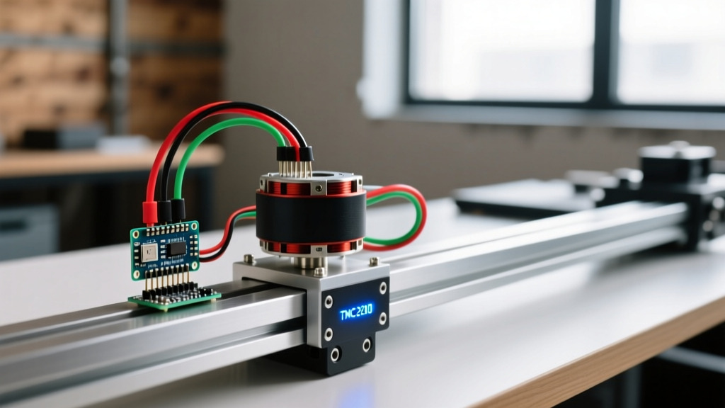
This guide details a real-world, heavy-duty camera slider build utilizing a NEMA 17 stepper motor, an Arduino Nano Every, and a Trinamic TMC2209 UART driver. We will cover the exact bill of materials, power delivery topology, current-limiting mathematics, and the software architecture required to eliminate missed steps.
2026 Bill of Materials & Cost Analysis
Choosing the right components prevents the most common failure mode in DIY sliders: thermal throttling and torque drop-off at high speeds. By utilizing a 24V power supply instead of the standard 12V, we effectively double the motor's high-speed torque envelope, a critical factor when moving a 5kg camera payload.
| Component | Specific Model / Specification | Est. Price (2026) | Purpose |
|---|---|---|---|
| Microcontroller | Arduino Nano Every (5V Logic) | $12.50 | Compact footprint, ATmega4809 processing power |
| Stepper Motor | StepperOnline 17HS19-2004S1 (NEMA 17, 59Ncm) | $14.90 | High holding torque, 2A rated phase current |
| Motor Driver | BigTreeTech TMC2209 V1.2 (UART Mode) | $8.50 | 256x microstepping, StealthChop2 silent operation |
| Power Supply | Mean Well LRS-100-24 (24V, 4.5A) | $21.00 | Stable 24V DC for high-speed torque retention |
| Mechanics | 2020 V-Slot Extrusion + GT2 6mm Belt Kit | $35.00 | Rigid linear rail with zero-backlash belt drive |
Total estimated electronics and mechanical cost: ~$91.90
Power Topology and Wiring the Stepper Motor Arduino Circuit
Wiring a high-precision slider requires separating the high-current motor power from the sensitive logic circuits. The Arduino Nano Every operates at 5V logic, which perfectly matches the TMC2209's VCC_IO threshold without requiring a logic level shifter.
Step-by-Step Wiring Guide
- Motor Power (VM & GND): Connect the 24V Mean Well PSU positive to the TMC2209 VM pin, and negative to the GND pin. Place a 100µF electrolytic capacitor across VM and GND as close to the driver as possible to suppress voltage spikes during rapid deceleration.
- Logic Power (VCC_IO): Connect the 5V output from the Arduino Nano Every to the VCC_IO pin on the TMC2209. This powers the UART and step/dir interfaces.
- Motor Coils (1A, 1B, 2A, 2B): Wire the NEMA 17 coils to the driver outputs. Verify coil pairs using a multimeter; pins with low resistance (typically 1.4Ω for the 17HS19-2004S1) belong to the same coil.
- Control Pins: Connect Arduino Pin 2 to STEP, Pin 3 to DIR. For UART configuration, connect Arduino TX (Pin 11 via SoftwareSerial) to TMC2209 RX, and Arduino RX (Pin 10) to TMC2209 TX. Note: Insert a 1kΩ resistor on the TX line to prevent bus contention.
Tuning the TMC2209: The Mathematics of Current Limiting
The most frequent cause of driver failure and skipped steps is improper Vref tuning. The TMC2209 uses an internal sense resistor (Rsense) of 0.11Ω on the BigTreeTech V1.2 board. Pushing the full 2A RMS continuous current through a NEMA 17 motor in a confined slider carriage will result in thermal shutdown within 15 minutes.
Expert Insight: For continuous duty cycles like a 2-hour time-lapse, we derate the motor current to 60% of its maximum. We target 1.2A RMS. This provides ample torque for a 5kg payload while keeping the motor casing below 50°C.
To set the hardware current limit via the Vref potentiometer, we use the Trinamic datasheet formula:
Vref = (Irms * 2 * Rsense) / 0.325
Plugging in our target values:
- Irms = 1.2A
- Rsense = 0.11Ω
- Vref = (1.2 * 2 * 0.11) / 0.325 = 0.812V
Using a multimeter, measure the voltage between the Vref test pad and ground while turning the trimmer potentiometer until you hit exactly 0.81V. Once set via hardware, the UART connection allows the Arduino to dynamically scale the current (using sgt and irun registers) based on the camera's position in the acceleration curve.
Overcoming Mid-Band Resonance and Mechanical Edge Cases
As documented in extensive stepper motor physics guides, NEMA 17 motors suffer from mid-band resonance, typically occurring between 1 and 2 revolutions per second. In a camera slider, this manifests as a visible 'shuttering' effect in the video footage.
Mitigation Strategies
- 256x Microstepping via UART: By utilizing the TMC2209's StealthChop2 mode and 256x microstepping, we divide the 1.8° full step into 0.007° increments, effectively smoothing out the magnetic detent torque that causes resonance.
- GT2 Belt Tensioning: A loose GT2 belt introduces a spring-mass harmonic oscillator effect. Tension the belt until it produces a low-pitch 'twang' (approximately 40Hz when plucked). Over-tensioning will bind the V-slot wheels and increase the motor's static load, causing it to draw excess current.
- SpreadCycle vs. StealthChop: While StealthChop is perfectly silent, it can lack the dynamic responsiveness needed for heavy payloads. If your slider stutters during the initial acceleration phase, switch the TMC2209 to SpreadCycle mode via UART. It introduces slight audible noise but drastically improves step accuracy under high inertial loads.
Kinematic Profiling with AccelStepper
Standard digitalWrite() step pulses will destroy your footage. You must implement a T-curve or S-curve acceleration profile to prevent the motor from exceeding its pull-in torque limit. The industry-standard AccelStepper Library handles the complex trapezoidal velocity profiling required for smooth starts and stops.
Below is the foundational architecture for the slider's movement logic:
#include <AccelStepper.h>

// Define pins (STEP, DIR)
AccelStepper slider(1, 2, 3);

void setup() {
  // Max speed in steps/sec. 3200 steps = 1 rev.
  // 100mm/sec travel at 20mm/rev = 5 rev/sec = 16000 steps/sec
  slider.setMaxSpeed(16000);

  // Acceleration must be tuned to payload mass.
  // 5kg payload requires a gentle ramp to avoid skipped steps.
  slider.setAcceleration(8000);
}

void loop() {
  // Move 100,000 steps (approx 625mm of travel)
  slider.moveTo(100000);

  // run() must be called continuously to process the T-curve
  while (slider.distanceToGo() != 0) {
    slider.run();
  }

  // Pause for time-lapse interval
  delay(5000);
}
Why run() Beats runSpeed()
Many beginners use runSpeed() for constant velocity. However, instantly commanding 16,000 steps/sec from a standstill will cause the magnetic field to rotate faster than the rotor's inertia can follow, resulting in a stalled motor and a ruined shot. The run() function continuously recalculates the required step delay, gently ramping up the frequency and ensuring the rotor stays perfectly synced with the stator's magnetic field.
Final Calibration and Field Testing
Before mounting your expensive cinema camera, perform a 'dry run' with a 5kg dummy weight (such as a sandbag). Run the slider through 50 full cycles. Monitor the TMC2209 driver temperature; if the heatsink exceeds 65°C, reduce the Irms via the UART irun register by 10% increments. Furthermore, verify that the Arduino Nano Every's 5V voltage regulator does not overheat when powered via USB during long time-lapses; if it does, power the Nano via the VIN pin using a dedicated buck converter stepped down from the 24V main supply.
By respecting the electromechanical realities of stepper motors and leveraging modern silent drivers, your stepper motor Arduino camera slider will deliver studio-grade, perfectly smooth motion in any real-world environment.